
When testing satellite communications links, there is often a requirement to use Commercial Off-The-Shelf (COTS) test equipment to simulate one or more link components.
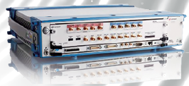
Keysight Technologies’ M8190A Arbitrary Waveform Generator
For testing transmitters, a spectrum analyzer or a high-speed oscilloscope with suitable software can be used to receive and analyze transmitted signals. Receiver testing may require a calibrated and repeatable signal source. Other components (e.g., transponders and amplifiers) may require a combination of both sides.
One of the key requirements is to generate test signals that are “realistic” enough to provide an accurate test, such as wideband communications signals, multichannel signals or even wideband chirp signals for ranging systems. A common way to create these complex test signals is to use an Arbitrary Waveform Generator (AWG) upconverted to transmission frequencies by a microwave source. With this hardware, and with software to create the signals for the AWG, it is not difficult to generate signals with bandwidths of several GHz at microwave and millimeter frequencies.
The most common limitation when using an AWG is usually the memory depth. To create wideband signals, a high sample rate must be used. Typical wideband AWG sample rates are frequently above 1 GHz and may be above 10 GHz. These high sample rates use up the AWG’s internal memory quickly, and most AWGs cannot play waveforms for more than a second without repeating. This creates a challenge for simulations that require slow variation of the signal over seconds or minutes, such as simulating the Doppler shift of a signal coming from a satellite in Low-Earth-Orbit (LEO).
Fortunately, recent advances in AWGs and sources now make these simulations possible. Advanced sequencing features allow the user to create long complex scenarios by recalling and repeating smaller waveforms. Digital upconversion (DUC) allows direct manipulation of the carrier frequency of a signal, allowing the same segment to be played at different amplitudes and frequencies without the need to store many unique segments. Advanced sweep capabilities in microwave sources allow for long sweeps over several minutes or hours, simulating the effects of Doppler shift on transmitted signals. How these techniques can be applied to simulating LEO Doppler shift will be examined in this article.
Equipment + Setup
All of the examples in this article use the Keysight M8190A AWG, which provides 14-bit signal depth at sample rates up to 8 GSa/s. The maximum frequency which can be generated by this AWG (staying in the primary 14-bit Nyquist range) is 3.2 GHz, so the Keysight E8267D PSG Microwave Signal Source to upconvert to microwave frequencies will be used.
Upconverting the Signal
There are two commonly used techniques to upconvert the AWG signal to higher frequencies using an external source (please see Figure 1). The first is to use an external mixer, with the AWG feeding the IF input of the mixer, and the source acting as the Local Oscillator (LO). The key to this method is to use the AWG to produce a signal already at IF, so that sidebands can be filtered off after mixing. This provides the cleanest signal in terms of in-band images, but it is limited in power, and requires the user to find a suitable wideband mixer.
In many applications, such as receiver test, power is not an issue, as the receiver is built to receive very small signals. It is also typically not difficult to find a suitable mixer for given frequency range. It is important that the setup includes a high-pass or low-pass filter to block unwanted mixer images. By setting the IF of the AWG high enough (while still containing the modulated signal within the AWG’s range), the two images can be spaced far enough apart to allow for an inexpensive filter.
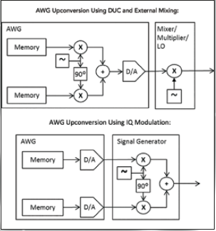
Figure 1.
In generating this signal, there is a significant advantage to using a “Digital Upconverter” (DUC). This DUC is in effect a “virtual” IF carrier independent of the AWG waveform. The upconversion to IF is done mathematically inside the AWG—parameters such as amplitude, frequency and phase can be changed completely separately from the baseband I and Q segments. In this way, long simulations of antenna sweeps, transponder paths, Doppler Shift and so on can be achieved over many minutes or hours without eating up the AWG memory.
Another method for upconverting the AWG signal to microwave frequencies is to use an IQ modulator, which are often available as an option within the microwave signal source. The biggest disadvantage to this method is usually the creation of in-band images: if the IQ modulator and its input signals are not tuned correctly, images and artifacts can show up in-band. Because the IQ modulator is built with less conversion loss than most external mixers, this method has the advantage of higher output power. It also has the advantage of convenience: by using the mixer built into the signal source, the user is free from sourcing and setting up external mixers and filters. This is the method used for the examples in this article.
Simulation Of LEO Doppler Shift
One useful application for the AWG and signal source is the simulation of the Doppler shift of a communications signal from a spacecraft in LEO. Doppler shift is the shift in frequency of a signal as a result of its velocity relative to the receiver. For a spacecraft in LEO, the Doppler shift increases the frequency of the communications signal as the spacecraft comes over the horizon into view. As the spacecraft passes overhead, the frequency rapidly shifts from a higher to a lower value, and as the spacecraft speeds away and over the horizon, the frequency levels out.
The equations for calculating this Doppler shift as a function of time are quite involved, but there are a number of papers available on the subject, one of which is listed in the references.
Calculating the exact profile of the Doppler shift involves the orbit height, the position of the receiver, the orbital path, and many other factors. Fortunately there are many software programs available online to perform these calculations.
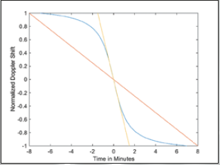
Figure 2. Typical Doppler Shift Profile with Two Linear Test Profiles
For the purposes of component testing it may not be necessary to precisely recreate the Doppler shift of the signal as a function of time. It should be sufficient to find out if the receiver will a) find and receive the signal at the maximum Doppler shift (at the horizon) and b) track and receive the signal while the Doppler shift is going through its fastest change (while the spacecraft passes overhead).
Rather than program the entire S-curve of the frequency shift, it may be enough to program in a linear frequency sweep, with the maximum and minimum points accounting for the highest and lowest frequencies, and the slope equal to or greater than the fastest expected transition (please see Figure 2).
As an example, a spacecraft in an 800 km LEO, transmitting at 12 GHz and in a path to travel directly overhead from the receiver would have a maximum Doppler shift of about +/-250 kHz, and a maximum transition slope of about 150 kHz/minute. Although the shift could be programmed as part of the digital upconverter within the arb, for this article, the “sweep” function of the microwave signal source was used to move the carrier frequency.
A simple linear frequency sweep can be used, or more complicated frequency paths can be made by sweeping through a list of frequencies in a linear approximation of the curve. Both the microwave source and the AWG’s DUC are capable of list sweeps with more than 10,000 points, allowing for many small frequency transitions per second over the long sweep.
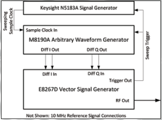
Figure 3. Block Diagram of the Test Setup
Changing the carrier frequency is only half the job. For wideband signals, the Doppler shift affects the symbol rate in the same proportion as the carrier frequency. Because the AWG’s sample clock is proportional to the symbol rate, changing the sample clock frequency will create the desired effect.
This is most easily accomplished by connecting another sweeping external source to the sample clock input of the AWG to adjust the symbol rate simultaneously with the carrier frequency (please see Figure at left). Trigger and marker signals can be used to synchronize the sweeps.
Creating a test signal with simulated Doppler shift involves not only changing the carrier frequency, but also the bandwidth of the signal. Test signals can be created using a wideband AWG and a microwave signal source.
Rather than using up the memory of the AWG on a long sweeping waveform, shorter repeatable segments can be moved around by varying the frequency setting of the signal source and the sample clock of the AWG.
Keysight Technologies: www.keysight.com/main/home.jspx?cc=US&lc=eng
References
Ali, I.; Al-Dhahir, N.; Hershey, J.E., “Doppler characterization for LEO satellites,” IEEE Transactions on Communications, Vol.46, No.3, Pp.309, 313, March 1998
Keysight Technologies Application Note: Solutions for Wideband Radar and Satcom Measurements (Document #5990-6353EN).