
RF Matrix Switches provide flexibility for Earth station operators to route signals in a large Earth station facility, teleport, cable headends, DTH (Direct-To-Home) and NOC’s (Network Operating Centers).
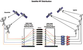
Figure 1.
This article reveals how RF Matrix Switches are commonly used in satellite facilities. Also discussed is the evolution of these key subsystems from legacy systems to the next-generation RF switches, which offer increased functionality as well as operational and economic benefits.
RF Matrix switches are often a critical core part of the infrastructure in Earth station facilities and are commonly used in multi-channel facilities for downlinking and uplinking signal management within the Earth station or teleport. An RF Matrix is a switch that routes Radio Frequency (RF) signals between inputs and outputs. Popular applications requiring RF matrices are satellite communications, broadcasting, military and government communication systems.
Although the term RF often refers to the Earth-to-space / space-to-Earth frequencies (e.g., C-, Ku-, Ka-band) in the satellite ground systems context, in the frame of reference of RF Matrix Switches, this typically refers to handling input/output switching and routing of signals at L-band (950 to 2150 MHz), Broadband (50 to 1000 MHz) and IF-Band (50 to 200 MHz).
Commonly, there are two primary RF switch matrices used in satellite facilities: Fan Out (Distributing) switches, which route an input to any number of outputs, and the Fan In (Combining), which take any number of inputs and routes them to a single output.
Matrices may be Symmetrical, i.e., having an equal number of inputs as outputs (such as 8x8, 32x32, 128x128, 2048x2048), or Asymmetrical, i.e., having an unequal number of input/output ports (such as 16x32, 48x96 or 128x256).
Applications
RF Signal Management in a NOC
RF Matrices are typically used to manage and route satellite signals within an NOC. The matrix provides a remote controlled, automated method to seamlessly route and switch downlink and/or uplink signals. A typical example: A major sports broadcaster in Los Angeles uses a Matrix Switch to route live, incoming satellite feeds within its facility to modems and/or receivers for sportscasts.
RF Matrix switches give Earth station operators the flexibility to route signals between different downlink and uplink chains involving other ground equipment, as depicted in the example in Figure 1, first column, bottom. An RF Matrix gives the NOC the ability to:
• Automatically switch inputs and outputs without patching or moving cables
• Reliably split and combine signals with no signal loss
• Redundantly power LNBs in an antenna farm
• Provide backup switching for 1+1 and N+1 redundancy and scheduled maintenance
• Automatically record the signal level of the satellite feeds
Signal Monitoring
Another common application is for service provider Signal Monitoring. Assuring customers that satellite signals are on-air and meeting specifications is critical to providers of quality of service.
RF Matrix switches are used as part of the on-air monitoring system that allows an Earth station operator to monitor and measure signals, such as downlink and uplink signals as well as return signals for compliance with expected parameters. A spectrum analyzer connected to a Matrix Switch can be configured to be time-shared within a facility, rather than dedicating the spectrum analyzer to a single input, which would be costly. The signal analysis device can be set up to continuously poll different inputs on the switch in order to monitor and record signal parameters across many RF signals.
Using an RF Matrix switch, a satellite facility can also save on equipment and resources by re-using the same satellite receivers by switching feeds between alternate antennas, or pools of receivers. Similarly, redundant units can be switched in case one unit fails or experiences a signal error, all done automatically or manually using a web GUI control or remote NMS.
Redundancy
A state of the art RF Matrix Switch, such as those manufactured by Quintech Electronics & Communications, Inc., can reconfigure signal paths in milliseconds and be configured to provide automatic signal path redundancy, so that an Earth station maintains optimal signal performance. If signals fall below a pre-set threshold, the switch can be made to a pre-configured backup input/output.
For example, if an input signal drops below a certain RF level, it would switch to a backup port. This can be pre-configured for 1:1 redundancy or 1:N, depending on the requirements. This means a facility can possess a variety of redundancy options and a high degree of flexibility, with easy operation.
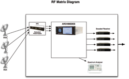
Figure 2. Signal Monitoring
In the case of Quintech, the company offers Q-ROUTE™ and Q-SENSE™ technology. This provides maximum reliability with signal path redundancy and auto re-route capabilities. Q-ROUTE™ provides internal signal path redundancy by automatically re-routing around a failed signal path. Q-SENSE™ provides external signal path redundancy by the automatic routing of back-up input signals.
RF matrices can also power LNBs. For example, the DEV Systemtechnik ARCHIMEDES RF Matrix Switch has an LNB power option. Each RF input port can deliver LNB power and select the polarity and the band of the LNB.
In addition the matrix provides an integrated TV receiver displaying a selected channel of the received satellite signal via the full HD multi-touch display. Optical inputs, unique redundancy options for inputs, outputs, controller and power supply add flexibility and functionality. The example in Figure 2 demonstrates multiple antennae being monitored using a single spectrum analyzer attached to an RF Matrix Switch.
The alternative to using such an automated switch would be manual patch panel connections—not an effective way to operate in most facilities with multiple signals and services. Manual patch panel switching can introduce cable patch panel “fatigue,” risk of electrical shorts, or danger of physical configuration errors. Changing physical connections may require a technician as well as the removal of floor or ceiling panels to change cabling and other labor related expenses. The use of a Matrix Switch eliminates the needs for these considerations.

DTH / Cable Head End RF Signal Management
A common application of large configuration (e.g., 100+ ports) RF Matrix Switches is in DTH broadcast centers and cable TV headends with large dish farms. Companies such as a DIRECTV, DISH Network, or similar satellite broadcasters around the world, may be downlinking and uplinking hundreds of signals on scores of transponders. All of these signals must be monitored and managed on a 24/7 basis.
An RF Matrix allows the operator to ensure that their signals are on-air. The DTH broadcast center (or headend) uses a large configuration L-band RF matrix switch to route and connect the transponder monitoring equipment and channel receivers so the headend can receive, switch, and monitor channels coming in from multiple transponders, satellites, and terrestrial sources.
Government monitoring and Intelligence agencies whose mission includes monitoring large numbers of satellite and broadcast signals, can also leverage the efficiencies of large-configuration RF Matrices in a similar fashion.
Teleport Services
RF Matrices are not just beneficial in Broadcast /DTH facilities with hundreds of signals. Medium, or small-configurations can also be critical in a teleport or facility providing Data, VSAT, IP, and satellite mobile backhaul services. Two examples include…
• Multiple satellite feeds routing to multiple receivers or modems
• Input level monitoring to detect loss of signal conditions
• Automatic redundancy to connect back-up signal on primary feed loss
Figure 3 on the next page depicts the example of a common teleport application for RF Matrices. In the example, on the uplink side, a Fan In matrix (in this case, the Quintech QFM allows the teleport to send many narrow data signals and combine them to a single transponder, for SCPC (Single Channel Per Carrier) applications.
An individual Modem, or Group of Modems/Modulators, can be combined and routed on selected outputs to specific Block Upconverters and sent to specific uplinks via the Block Upconverter to HPA transmit chain. The RF Matrix can route individual SCPC modem signals to a designated satellite transponder, or uplink path.
By using the RF Matrix (in this case, the Quintech QFM), the operator can easily select which modems to combine on an uplink. Downstream signal paths to IP infrastructure, IP terminal equipment, or video encoding equipment, can be easily switched between primary and backup redundancy uplink chains via remote and automated control.
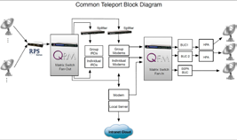
Figure 3. Teleport Block Diagram
On the Downlink, carriers coming into a QRF Fan Out Matrix can take the inputs from the L-band antenna cable and fan them out to the different IRDs, or demodulators/modems. If an Earth station operation is frequently re-allocating services, carriers, and connecting different terminals to different uplink channels, an RF Matrix lets operators mix and match input/output paths seamlessly, either automatically, or under
operator control.
High Throughput Satellite (HTS) Ka Band System Gateways
HTS gateway Earth stations may require the ability to route and switch RF signals between diverse uplink and downlink device chains within a spot beam or polarity, depending on the architecture and traffic requirements. RF Matrix switches can be used to automatically control L-band signals routing between HTS RF signal chains and ground connections.
Outside Broadcast/Mobile/Satellite News Gathering Systems (SNG)
Smaller Matrix Switches are also used in live production, SNG and maritime environments. For example, sports outside broadcast (OB) mobile uplink vehicles may need to send multiple outgoing content to satellites and may need to monitor the return signal, creating a SNG need for a smaller Matrix Switch.
An example of such a switch, is the DEV Systemtechnik 82 (Eight-Squared) L-Band Matrix Switch, to be introduced at the 2015 IBC Convention. SNG friendly features, such as LNB powering, flexible inputs and outputs, optical inputs, unique redundancy options, LNB powering, full color display user interface, and dual redundant field replaceable power supplies, provide the most reliability and flexibility available in its class. The 1RU 82 is also suitable for various redundancy purposes and can be operated in autonomous mode.
Technology Evolution: Expanding Functions, Reducing Overhead
Older, large-configuration, legacy RF matrix switching systems require miles of coaxial cable and thousands of watts of power to operate. They can be quite labor-intensive for satellite ground facilities to install and to maintain them. Older generation RF matrices are unable to seamlessly integrate with modern Network Management Systems (NMS), IT infrastructure and terrestrial fiber systems.
The evolution of RF matrix switches over the last 20 years has led to some game-changing reductions in energy use, form factor and performance. Quintech’s next-generation L-Band Matrix Switch, the XTREME 256, (a 128x128 scalable L-Band symmetrical/asymmetrical) Matrix Switch meets this challenge.
For example, the switch offers greater than six-fold (6.5X) reduction in electrical power consumption, while saving more than 3.5 miles (5.6 km) of RF cable runs per comparable system. The system greatly increases broadcast and teleport facilities’ operational capabilities, while vastly reducing power requirements, cabling and rack unit footprint. The business case for replacing older, large-configuration legacy RF matrix switching systems with this nexgen system can provide a high return on investment (ROI).
Another example of this kind of improvement is the company’s nexgen matrix for mid-sized systems, ARCHIMEDES, which also sets a new performance benchmark in the size and price for L-band matrices, allows from 16x16 up to 64x64 in symmetric or asymmetric configurations in only 4 RU, while consuming 75 percent less power than competing products.
Expansion By Reduction
In today’s environment, organizations continue to face ever-increasing demands for bandwidth, content distribution and data processing. At most facilities, pressure to manage operating expenses and the demand to increase energy efficiency has never been more important.
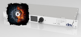
Figure 4. Example of a rack unit matrix for Mobile / SNG.
Nexgen RF Matrix Switches—such as Quintech’s XTREME 256—offer an exciting opportunity for the satellite industry to refresh legacy L-band matrices and greatly increase operational capabilities,all the while vastly reducing power requirements, cabling and rack unit footprints. For new ground facility builds, for example, to serve High Throughput Satellite (HTS), where requirements can exist to switch between multiple RF paths, new RF matrices can also provide similar efficiencies.
Similar efficiencies for new RF matrices also exist for new High Throughput Satellite (HTS) ground facility builds, where requirements to switch between multiple RF paths can occur.
James Rapach is an RF Design Engineer and received his BSEE from the University of Pittsburgh.
em>Quintech Electronics and Communications, Inc. is a leading manufacturer of RF signal management communications equipment. Quintech designs and manufactures RF matrix switches, RF-over-fiber, routers, redundancy switches, relay switches, splitters, combiners, amplifiers, frequency converters and DC powering products.