

In this TechTalk feature, a novel approach for remote sensing, communications, and tracking via satellite is presented. Vulcan Wireless (VW) has developed a system that allows low-cost low-power tags to communicate via satellite. This approach is most appealing for low data rate applications in areas where infrastructure is limited — that is, rural environments. It is also highly appealing to coexist with tags that work in more urban environments.
 DIRECT COMPARISON OF LPWA TECHNOLOGIES PART II
 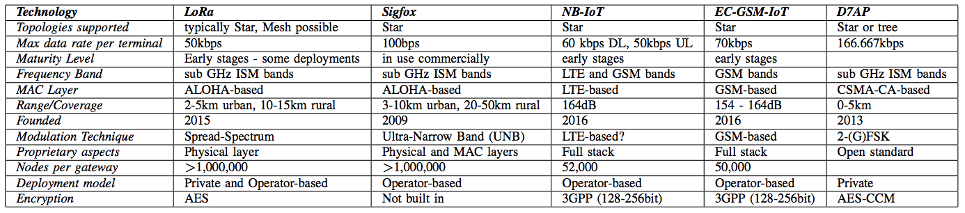 DIRECT COMPARISON OF LPWA TECHNOLOGIES PART I
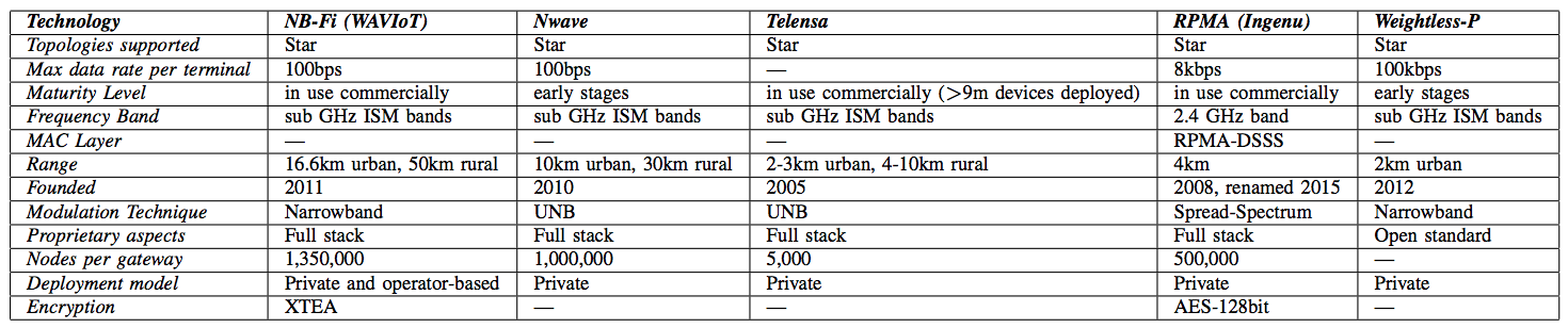
Figure 1. Comparison of Low-power wireless technologies, excerpt from1
Some of the key applications for this tag include:
• Pay-per-use bicycle/scooter tracking. These devices can usually be tracked throughout the city by the urban infrastructure (cellular, wifi, specialized base stations, etc…), but at times these devices do not have local connectivity. With the Vulcan Tag the device can phone home even when no cellular is available.
• Emergency 911 services for wearables. These small light-weight tags can be embedded in safety hats, jackets, and cellphone cases. By working with your cellphone they allow your cellphone to send text messages, tweets, 911 calls, even when no cell tower is around.
• Agriculture sensors are another unique application that is well-suited to this TAG. These sensors can be deployed throughout growing fields where they are monitoring humidity, crops, etc.. and reporting back information via satellite without establishing an expensive infrastructure.
• Supply-chain monitoring is another important application. Truck trailers and pallets of materials can be tracked throughout the transportation cycle for big data management.
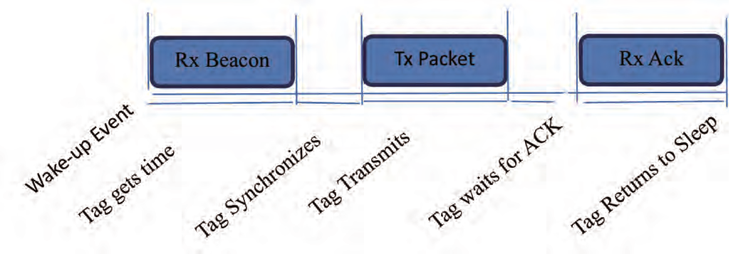 Figure 2: Tag wakes up and uses the beacon to set its clock, then transmits listens for acknowledgement and goes back to sleep.
Competitive Landscape
Today, there are many low power tag options and many satellite systems new and emerging, but our unique technology has been designed for a special set of applications.
Some of the existing tag options are: LoRa, Sigfox, NB-IoT, NB-fi, Nwave, RPMA, etc… as shown in Figure 1.
A key difference between these existing systems and Vulcan’s new approach is that these existing methods require a local infrastructure to operate. That is, either a LAN or WAN infrastructure. These usually manifest itself by WIFI access points or cellular base stations. The TAGs in our system do not require a local infrastructure.
The Disadvantaged TAG
For a low-power tag to communicate with a satellite is a challenging problem and is accomplished by fusing a number of key technologies.
Figure 3. CubeSat with antenna array directing its beam to a particular
area of interest.
The communication link is a two-way link: the Uplink and the Downlink. The Uplink is the more challenging of the two. On the downlink, the TAG is the receiver and the satellite is the transmitter. In this case, the satellite is designed to have higher power and the receiver has less interference since the number of overhead emitters is sparse.
However, the uplink creates a different situation. Here, the TAG is the transmitter and the satellite is the receiver. In this case, the TAG is a low solar powered device, so it cannot afford to have a large power amplifier on the TAG, and the satellite’s receive antenna is capturing electromagnetic emissions from a significant footprint on the Earth, which allows the satellite to capture emissions not just from the TAG but also captures significant interference from TAGs and other devices.
Although the satellite antenna aperture is larger than the TAG’s aperture, it is limited in size to enable use on a CubeSat. This combination creates a challenge on the Uplink.
On the uplink, a key link budget statistic is the received carrier to noise ratio at the satellite. To improve this link performance, every adjustable aspect in the link budget is optimized. The data rate is lowered to increase the coding gain, add a phased array antenna, optimize the gain and directionality of the TAG antenna, null large interferers with spatial directionality, and remove interferers temporally as well.
By lowering the operational data rate the time duration of an information bit is effectively increased. Since the energy per bit of information is equal to the carrier to noise density times the bit duration the available
Energy per bit to Noise Density increases with lower data rate.
Technology
Sensor Protocol
Each sensor is built with a unique ID/Serial Number that is set in the factory when firmware is loaded onto the Communication’s TAG. The TAG also needs configuration parameters to specify how the TAG is utilized. These parameters include: How the Serial ID maps to a Spread Code, the center frequency, the hopping pattern algorithm, the number of retries, and the duration for the TAG to Check-In.
The Check-In time refers to if the TAG should report health periodically even if a detection event has not occurred. This Check-In time can be configured to durations like: once a day, once a week, or never.
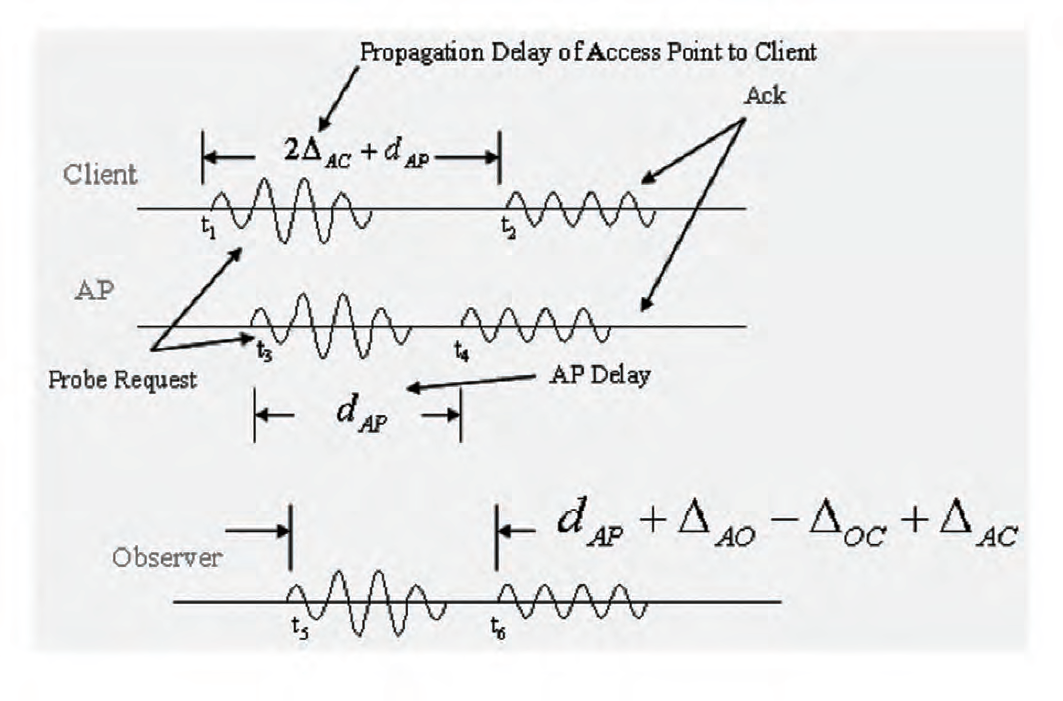
Figure 4: Illustration of Time-of Arrival Ranging, excerpt from2
Once the configuration parameters have been loaded and the TAG has been deployed, the TAG wakes up if the connected sensor has an event such as “Audio Detection,” or the Check-In timer causes the wake-up event.
At wake-up, the TAG sends a packet to the Gateway, and the Gateway responds shortly thereafter. The response is an acknowledgement so that the TAG does not have to resend its message. Certain configuration information can also be changed with the acknowledgement, such as programming a new Check-In time. The TAG then goes back to sleep and waits for the next event.
When a wakeup event occurs, the TAG must first adjust its clock. When the TAG is sleeping, its clock is active and running in a very low-power state consuming less than 1 uW of power. The protocol is illustrated below in Figure 2 below. The TAG wakes up at a wake-up event, listens for the Downlink to update its time, transmits its information, waits for its acknowledgement, and then goes back to sleep waiting for its next wake-up event.
Scalable CubeSat Constellation
The system that is proposed is genuinely scalable. Operation can start with a single CubeSat or fixed gateway or aircraft or drone, etc...
A single CubeSat can provide worldwide coverage. However the time for which the CubeSat is visible to the TAG is limited. A typical pass might be for 6 minutes every 90 minutes.
As more CubeSats are added to the constellation the coverage becomes more complete. Also, as the coverage becomes more complete then the capacity of the system also increases since each CubeSat has a fixed maximum capacity. Similarly, by adding additional drone, balloons or fixed base stations one improves both capacity and coverage time over smaller areas.
GPS Elimination
Today GPS receivers are constantly reducing their cost and SWAP (Size, Weight and Power). The Vulcan TAG approach supports external GPS receivers as well as the elimination of the GPS receiver. By eliminating the GPS receiver the TAG reduces both hardware and antenna requirements.
The lowest cost version of the TAG supports two-way time transfer to the satellite. Accurate time transfer is done by having both the TAG and the satellite work together.
The TAG sends its message at a fixed offset from listening to the satellite and hearing a beacon. The satellite uses this information to trilaterate the TAG. If multiple CubeSats have coverage of the TAG, then they can fuse the information for more reliable location estimates. Similarly, a single CubeSat can get more reliable location information of the TAG by having it report back at multiple time instants.
As shown in Figure 4, accurate timing information is determined by using precise timestamps of sending and receiving waveforms using time-of-arrival methods.
C-Band Phased Array
Where Dt is the directivity of the transmitting antenna, and Dr is the directivity of the receiving antenna, “Lambda” is the wavelength of the electromagnetic wave being used and D is the distance between the transmitter and receiver. Note, equation (1) can be very misleading when one is comparing different frequency bands since the transmitted and received Directivity depends upon frequency. The more useful formula is Friis’ original transmission equation:
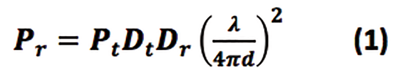
Equation 1
Where Dt is the directivity of the transmitting antenna, and λ is the directivity of the receiving antenna, is the wavelength of the electromagnetic wave being used and is the distance between the transmitter and receiver. Note, equation (1) can be very misleading when one is comparing different frequency bands since the transmitted and received Directivity depends upon frequency. The more useful formula is Friis’ original transmission equation:
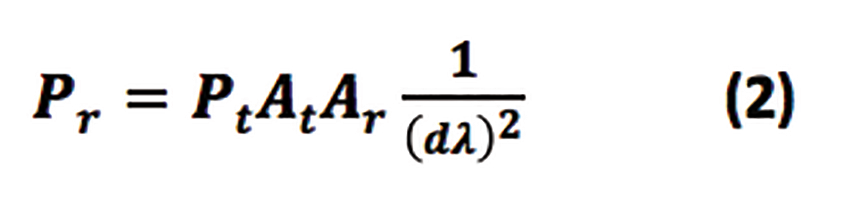
Equation 2
where At is the effective area of the transmitting antenna, and Ar similarly is the effective area of the receiving antenna.
In the past, Equation (1) was well-used as system designers compared the same antenna design (e.g., monopole) at different frequencies where only the size of the monopole would change. However, Equation (2) clearly illustrates that the received power increases as frequency increases for a fixed distance when antenna sizes are fixed. Multiple choices can be used for the antenna selection at a particular frequency such as a dish or antenna array. The antenna array is particularly useful on the CubeSat platform since elements can be placed on the CubeSat structure or deployable solar panels.
The CubeSat antenna consists of an array of antenna patches to electronically steer the downlink to a specific location on Earth. The weights of the antenna elements are adjusted to maximize the transmit gain on the TAG.
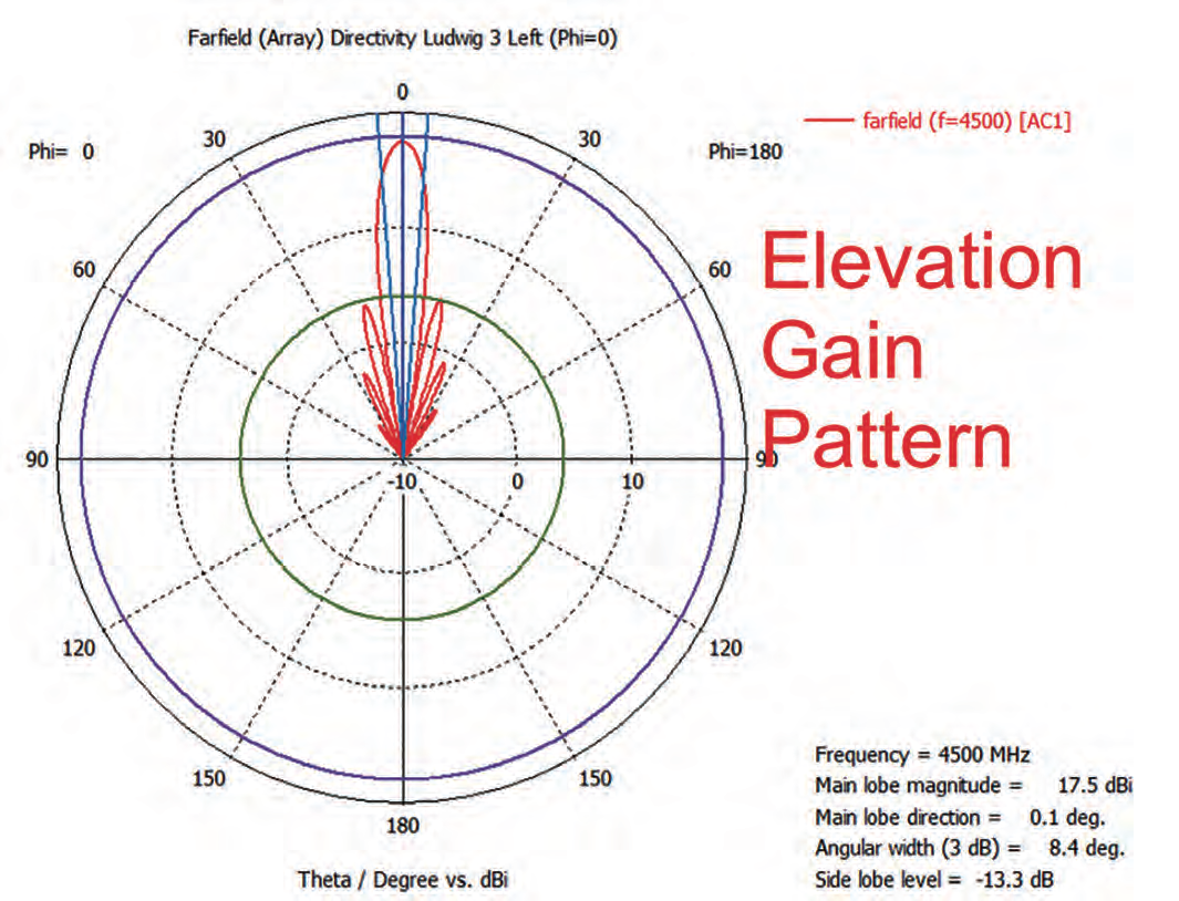 Figure 5: Beam pattern of an individual element from CubeSat’s phased array.
Similarly, for the uplink the weights are adjusted on the CubeSat to maximize the gain from the TAG and minimize external interference from other sources. In Figure 5, the gain pattern of an individual element of the phased array is shown. The narrow beamwidth provides excellent shaping in the electronically steered array.
On the TAG, a patch antenna this gives excellent directivity for the TAG to point overhead for transmission and reception is used. The TAG naturally points upward, this maximizes gain to the passing CubeSat while minimizing ground-based interference.
Waveform Design
Spread spectrum waveforms are very important to the design of the TAG system. By spreading the signal over a large frequency band interference rejection is significantly improved.
The interference rejection is done in cooperation with interleaving and error-correction coding. If the frequency band is corrupted or jammed and communication is attempted in this band then the communication will typically fail. But if the signal is spread over a larger bandwidth then a narrow band interferer only corrupts a portion of the signal which is corrected by the combination of interleaving and error-correction coding.
Conclusion
Vulcan Wireless is developing a state of the art space-based TAG system for communication and geo-location in remote areas. The development to date includes developing the flight hardware and a demonstrable TAG to satellite communication system that has been tested in Lab and outdoor environments.
www.vulcanwireless.com/
References
1A Comparative Survey of LPWA Networking, J Finnegan, S Brown - arXiv preprint arXiv:1802.04222, 2018 - arxiv.org
2Golden, Stuart A. and Bateman, Steve S.. “Sensor Measurements for Wi-Fi Location with Emphasis on Time-of-Arrival Ranging.” IEEE Transactions on Mobile Computing 6 (2007):.
Vulcan Wireless has extensive experience in developing digital radio solutions for small satellites and sounding rockets. Many customers have chosen Vulcan Wireless radios for their satellite missions due to Vulcan’s experience of meeting quality, reliability, functionality, and cost requirements. One such example is the NASA JPL ASTERIA mission. This mission used the Vulcan Wireless Radio for its CubeSat to study stellar activity, transitioning exoplanets, and other astrophysical phenomena.