
Any satellite communication system is required to balance bandwidth and power distribution over the coverage defined by its target market. Inmarsat has been operating global satellite communication systems servicing the mobile market space, including aviation, for more than 30 years. In this article, the differences between the current and upcoming satellite communication networks are explained to potential users to allow an accurate assessment of which offering could satisfy their communication needs.
The Inmarsat-5 network will offer global coverage via three, geostationary Ka-band satellites, providing uniform coverage in both bandwidth and power with the flexibility to move bandwidth into regions where traffic requires it. The selected spot beam architecture supports an uniform distribution of power, allows for frequency re-use and, ultimately, allows a consistent end user experience.
Couple this with a complete turnkey satellite and ground infrastructure with everything owned and operated by a single entity and built for scalability, resilience and performance, and there will be clear differences in the resulting service offering and reliability between this constellation, built for mobility from the outset, and that of the existing Ku-band service providers. Generally speaking, these providers collate patchwork networks through third party agreements with multiple satellite operators with systems that were originally deployed to address alternative communication needs.
Introduction To Communications Channel Theory
Before assessing the performance of any communication channel, it is essential to understand the communications systems governing theory. Shannon’s Theorem [1] gives an upper bound of the throughput capacity of a link in bits per second (bps), as a function of the available bandwidth and the signal-to-noise ratio.
The theorem shows that there are only three key parameters that can be manipulated in order to optimise the capacity of a communications link: Bandwidth, Signal Power and Channel Noise. Communication channel providers develop their technologies in order to achieve the optimal link capacity based on their market needs and this document examines the Inmarsat-5 optimisation with a view to serving the mobile communication market.
Signal Power + Distribution
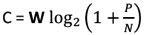
The formula at right shows that an increase in the transmit power level results in an increase of the communication link throughput, likewise a decrease in power will result in the opposite effect reducing the throughput. Power can be independently adjusted in both the forward and return link directions.
Signal Strength Impact Explained
As an example, the higher the output power at the transmitting antenna, the higher the modulation coding rate that can be achieved and ultimately the higher data rate can be realised for the user. Another way to improve the link throughput would be to increase the size of the receiving antenna in order to have a higher level of energy received at the aircraft; this is where operational constraints become apparent, as, this would lead to an unfeasible installation for a commercial or business aircraft.
It would also be possible to increase the signal strength from the satellite; however this would mean focussing the satellite spot beams over a smaller area to the detriment of the overall satellite coverage as on-board power cannot be increased freely, due to satellite power being limited; similarly power in any single spot beam cannot be increased freely due to the limitations in space qualified amplifier equipment availability. In the opposite direction, i.e. from the aircraft to the satellite, the transmitted power is limited by regulatory requirements meant to protect adjacent satellites from harmful interference and therefore must be properly managed.
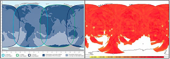
Figure 1. Inmarsat 5 Coverage and Power Level Distribution3
The Inmarsat-5 satellite constellation provides a global coverage through a combination of two on-board communications payloads, the Global Service Beams (GSB) and the High Capacity Payload (HCP). The GSB payload uses small spot beams (approximately 2 degrees wide) to build the global coverage footprint and uniquely distributes the power evenly across their footprint. With the lattice of spot beams established, the result is a higher, more focussed power for use. The GSB is then supplemented by the HCP which can independently steer six ~1.2- degree wide beams, every beam supporting 8 x 100MHz channels, on each satellite across any area that requires additional capacity on demand. Figure 1 shows the global coverage of the constellation and the power level distributed by the GSB payload only.
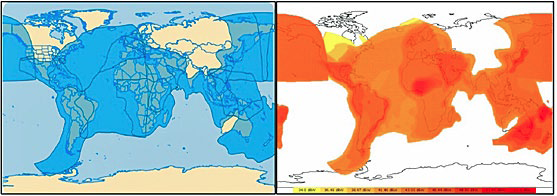
Figure 2. Intelsat Mobility Fleet Coverage and Power Level Distribution4
This spot beam architecture is in contrast to all existing Ku-band satellites that utilise wide beams to provide their regional coverage. The wide beams have in general a lower overall power density and higher variance of power across their footprint. Figure 2 on the previous page shows the footprint and power levels across the Intelsat mobility fleet.
The coverage charts show that Inmarsat-5 offers a greater global service, however it is also clear from the plotted power levels that the average power available for use on the Intelsat wide beams is considerably lower than for Inmarsat-5. The result is lower throughput for the users on the Ku-band network and the higher variance of power results in a varying end user’s experience as the user moves within the beam.
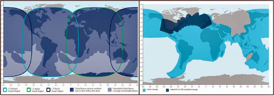
Figure 3. Inmarsat-5 and Intelsat EPIC High Throughput Spot Beams5
As described in public information, Intelsat EPIC is Intelsat’s upcoming new generation satellite constellation, operating in Ku-band, with one satellite under construction (IS-29e) and one other planned. This satellite will offer spot beam coverage, similar to Inmarsat-5, over some of the North Atlantic air routes and overlay a wide beam for the remainder of its coverage region. This scheme will result in high power and performance in some areas and lower performance in others. Figure 3 on the previous page shows a comparison of the wide beam Intelsat coverage (light blue) with the IS-29e EPIC spot beam coverage (dark blue) overlaid next to that of Inmarsat-5.
Bandwidth Availability + Management
Within Shannon’s Theorem it is shown that another means of increasing the upper bound of the communication link is to increase the bandwidth.
Bandwidth Contention Explained
To understand how bandwidth can be maximised within a communication channel, it is important to consider the issue of bandwidth contention. This is effectively like an airline deliberately overselling tickets on a particular flight on the premise that not everyone will arrive to travel, however when everyone does, someone must be left behind.
Telecommunication spectrum is a scarce resource, and therefore spectrum allocations are used to saturation by the operators.
Inmarsat-5 operates in Ka-band which not only has a larger frequency allocation (approximately 9 times larger depending on the region of operation) but is also still relatively unoccupied compared to the Ku-band. Figure 4 below shows the difference in allocations between the bands.
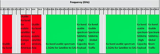
Figure 4. Spectrum Allocation Compared6
As discussed in the previous section, Inmarsat-5 operates a spot beam architecture that allows a uniform distribution of capacity and bandwidth. The constellation evenly distributes capacity across the GSB spot beams and implements a seven colour frequency re-use scheme to allow for frequency re-use to be implemented and further optimise the allocated spectrum. Where traffic profiles demand, the GSB spot beams can have a further transponder assigned as required and if the traffic profile still demands additional bandwidth the HCP can steer a beam into the area to accommodate the additional users. To quantify this overall bandwidth capability, a single GSB beam can provide up to 50Mbps, therefore where a second transponder is assigned a further 50Mbps will be available and the HCP could add up to an additional 120Mbps for every allocated channel (of which there could be eight simultaneously) in a given region.
On comparison of Ku-band wide beam coverage to that of the Inmarsat spot beams covering the same area, it can be shown that the Inmarsat-5 constellation will apply more capacity in any one region than the equivalent Ku-band satellite. This is shown in Figure 5 along with a comparative capacity calculation. Due to the larger Ka-band frequency allocation and that these allocations are not currently being shared, the chances of bandwidth contention are reduced significantly. The competing Ku-band systems are disadvantaged by their saturated frequency band and by the density of Ku satellites already deployed along the GEO arc which do not provide sufficient and adequate “free slots” to accommodate forecasted and in some cases current traffic demands. We believe the availability of Ku-band transponder capacity for aviation service providers is already limited in many geographical areas.
Like For Like Capacity Calculation
The below example provides the transponder capacity calculation available within the two example satellite regions shown within Figure 5. below. It is important to note that Ku-band satellites such as
IS-22 share transponders for traffic in both directions; Inmarsat-5 has independent transponders for each traffic direction.
• Ku (IS-22)
»12 x 36MHz = 432MHz
»Shared amongst various services including fixed satellite services i.e. TV and media
• Inmarsat-5
»38 spot beams cover the same regions
◊ 2 x 32 MHz x 38 beams = 2.4GHz
»Additional scalable High Capacity Overlay available with up to 8 x 100MHz channels available in a specific region
◊ 2 x 100MHx x 8 channels = 1.6GHz
»Dedicated to mobile service use
The example shows Inmarsat-5 has almost six times more capacity assigned within similar regions of satellite coverage with the GSB beams that can then be further supplemented with HCP beams if the traffic profile demands.
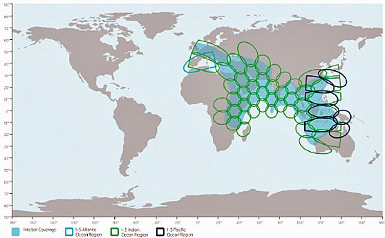
Figure 5. Ka-band Spot Beams Capacity versus Ku-band Wide Beam Capcity7
Public information reflects that the upcoming Intelsat EPIC satellites will focus bandwidth into the spot beams covering some of the North Atlantic flight routes and then have capacity within a wide beam for the remainder of its footprint. The transponder sizes and bandwidth management scheme of the upcoming satellite has not been published and therefore it is very difficult to fully assess the capacity of the channel.
This configuration may raise its own issues in terms of bandwidth contention however, as where there is an overlay of spot beam to wide beam, frequencies cannot be shared. From available public information, we believe the IS-29e may therefore run into frequency constraints, unless a new method of frequency management is planned but not yet disclosed.
Network Technology Advantages
The Inmarsat-5 ground segment is based on the latest version of the highly successful iDirect Evolution platform, not available to other users. This significantly increases the channel density supported on each piece of hardware. The system supports seamless handover between beams and load balancing of users among multiple channels in the same beam, all of which requires a new approach to system scalability.
The network will consist of three pairs of Satellite Access Stations (SAS) located around the globe, with each pair serving one satellite to provide rain-fade protection through diversity of the feeder link, and complete failover in the event of a catastrophic disaster. SAS sites and strategic network peering points are connected together in a redundant global ring.
The Inmarsat-5 constellation, terminals and ground network have been designed and implemented with mobility as the primary application with the global coverage and high performance spot beam architecture as described within this paper only part of the overall system advantage.
The entire end-to-end system is built and owned by Inmarsat, with the ground infrastructure duplicated in each region. This end to end approach delivers a more resilient, higher performance and more cost effective network than other solutions that interconnect leased capacity from multiple satellite providers across their respective regional coverage. This benefits the end users through providing a completely homogenous network and terminal infrastructure with seamless handover functionality and all resources managed and controlled from a single point. With each region’s ground infrastructure duplicated offering resilience from local interference or equipment failure, the turnkey implementation is very different to the competing mobility offerings from other service providers. Other providers patchwork services together through lease agreements from several satellite suppliers resulting in more complex ground architectures and harder handover co-ordination.
Summary
In summary to the analysis carried out, the authors believe the Inmarsat-5 constellation has clear and significant advantages over the existing and future Ku-band mobility satellite systems. The larger relatively unoccupied Ka-band frequency allocation makes it ideal for global mobility solution. This is because the use of spot beams can evenly distribute higher power levels across the satellite footprint and manage frequency assignments flexibly to suit traffic demand.
This suitability for mobility is further supported by the turnkey implementation approach taken by Inmarsat with all infrastructure owned, operated and managed by a single operator and implemented as a homogenous network with both ground and mobile technologies built by the same suppliers.
The frequencies are allocated and controlled from a single point along with the satellites within the region therefore alleviating any dependence on ad-hoc patchwork agreements between multiple satellite service operators with distributed networks and complex data backhaul architectures attempting to provide a single service to a third party.
Toward the end of the decade, we expect satellite constellations such as Intelsat EPIC will enter into service and move toward spot beams in the Ku-band to increase the power and manage the bandwidth available in specific regions. However, we do not anticipate that these regional based services will answer the call for a global mobile satellite service as effectively as the Inmarsat-5 constellation.
Footnotes
1 Technical Marketing Manager, GX Aviation – Inmarsat
2 Vice President Global Xpress Commercial – Inmarsat
3 Inmarsat-5 coverage and power distribution provided by Inmarsat
4 Intelsat Mobility Coverage from website, February 2013
5 EPIC Spot Beam coverage from Apex blog: http://blog.apex.aero/cms/wp-content/uploads/2012/07/Panasonic-Intelsat-map-2.jpg
6 Frequency Allocations governed and published by the International Telecommunications Union (ITU) Radio Regulation Articles 2012
7 Inmarsat spot beam layout from Inmarsat, Intelsat IS-22 wide beam coverage.
References
C.E Shannon, “Communication in the presence of noise,” Proceedings of the Institute of Radio Engineers
Intelsat website: www.intelsat.com
APEX Blog: http://blog.apex.aero