
Ka-band is changing the face of satellite communications. Enabled by satellites having significantly higher capacity, Ka-band is delivering on its promise of low cost highly efficient communications.
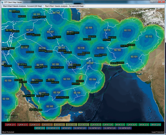
Figure 1. Sample HTS coverage area.
Ka-band used to deliver satellite broadband to home users and enterprises, the applications for Ka-band also extend into the maritime, aerospace, and defense sectors. Widely referred to as third-generation broadband, or High-Throughput Satellite (HTS), these systems are capable of delivering more than 100 Gbps of data and servicing over one million users. This is 10 to 100 times the capacity of traditional wide coverage area systems. This is a significant increase in capacity; the primary motivator for HTS is to provide more bandwidth at a lower price per bit.
What is different about these Ka-band systems? First, the contiguous Ka-band spectrum reserved for satellite services is significantly wider than it is for Ku- or L-band. This provides larger bandwidths and inherently higher data rates. Additionally, Ka-band HTS are typically designed with payloads that have many narrow spot beams and high frequency reuse, as compared to the wider coverage areas and low frequency reuse of Ku-band payloads. These aspects, combined with the use of today’s most modern modulation techniques, result in a system with much higher capacity.
The Need For Capacity Management
Whether you are a satellite operator, service provider, or network operator, you know that the satellite resource is your largest expenditure and that the ability to maximize performance and utilization of that asset is the key to a profitable venture. To accomplish this task, you must dynamically manage your satellite resources initially and as capacity increases. Ka-band systems bring larger bandwidths, more spot beams, higher throughputs, and new gateway and payload designs. This is demanding new and innovative capacity management and planning toolsets that address the complex issues associated with Ka-band and high capacity systems.
Deep Rain Fade Impacts @ Ka-Band
Higher frequency bands such as Ka- are more susceptible to weather effects than lower frequency bands. The most significant weather effect concerning Ka-band is rain, with the largest attenuations occurring during relatively short periods of intense rainfall (up to 30 dB, in some cases). To compensate for weather effects, Ka-band systems are designed to mitigate deep rain fade. Generally, the overall system is designed such that the forward link performance is dominated by the terminal downlink, while the return link performance is dominated by the terminal uplink. The idea here is that the gateways can be designed for operation at specific locations, whereas terminals are required to operate where needed.
The result is a gateway segment that provides a highly available feeder link. Techniques used to accomplish this including planning the gateway locations in dry areas, using redundant gateways to add site diversity, implementing uplink power control, and using transponder automatic level control (ALC) when practical.
Accurately modeling Ka-band propagation impairments and rain fade mitigation techniques are essential to planning capacity and designing robust satellite links. Without this it will be difficult to deliver the availability requirements to meet your company’s service level agreements (SLA).
As more Ka-band systems come into operation, more experience and knowledge regarding the frequency is being acquired and studied. This is leading to revised propagation models, updated climatic data, and new system designs for rain fade mitigation.
Consequently, the propagation models are changing—much more rapidly than in the past. To remain effective, capacity planning tools need to be flexible in accommodating updated models and data files. To assist, SED offers pluggable software modules that implement the latest ITU-R propagation models and software libraries for modeling site diversity improvement, uplink power control, and transponder ALC.
Interference Considerations @ Ka-band
Comparatively, Ku-band is much more widely used with almost all orbital slots occupied. With Ku-, interference to adjacent satellites is often the limiting factor in terms of terminal size for the return link. Ka-band has a better interference environment and its use in practice is limited to small terminals
Figure 2.
Additionally, the Ka-band spectrum allocated to satellite communications is not currently allocated to any terrestrial services on a primary basis. Interference with adjacent satellites and terrestrial services can be thought of as external interference, and although important to consider for Ka-band, is not as dominating as it is for Ku-band.
What is more important for Ka-band is the consideration of internal system interference. HTS Ka-band systems employ high-gain narrow spot beams and large amounts of frequency reuse. Adjacent beams use different frequencies, polarizations, or combination thereof.
The number and size of the spot beams vary between systems, but generally the spots cover several hundred kilometers, with the larger systems having upwards of 200 spot beams. Depending on the number of gateways deployed and the amount of bandwidth available in each beam (50 to 600 MHz), frequency reuse can be up to 20 times.
Depending on the satellite antenna technology used and corresponding transponder levels, the isolation between beams reusing the same frequency can vary between 20 and 30 dB and, in some cases, be less than 20 dB. Understanding the impacts of frequency reuse and beam power allotments are critical to operating a multi-spot beam system.
SED offers software to analyze and visualize beam coverage patterns and beam-to-beam isolation for multi-spot beam systems of varying sizes from a few beams to hundreds beams. Co-polarization, cross-polarization, and combined modes are supported. Coverage analysis functionality displays contours either relative to beam-peak or to edge-of-beam. Isolation values can be displayed as heat maps with a configurable resolution and color gradient. Given a carrier load, the software will compute the level of induced and incurred interference in beams using overlapping frequency. Using these tools, the carrier to interference noise can be effectively managed by trading off interference levels with beam loading.
Adaptive Coding + Modulation
Most Ka-band systems deploy some form of adaptive coding and modulation (ACM) technique to maximize the data rate of the satellite channel while providing robustness during times of weather induced fade. Whether it is DVB-S2 or the recent S2X extensions for the forward link, or a proprietary variant of multi-frequency TDMA in the return link, the goal is to design the links to maximize the possible data rate while delivering the quality required.
As each terminal’s operational environment will differ, these adaptive systems work at the terminal level. In real-time, the system continually evaluates the performance of each terminal link and dynamically changes the modulation and coding techniques (MODCOD) and symbol rates to adapt.
Most high-throughput satellite systems operate on the premise of a group of terminals sharing one or more satellite channels. The idea is to maximize the number of users serviced. This is done by leveraging the dynamic nature of the individual terminal links and traffic demands.
Some terminals will be experiencing rain fade and require the use of more robust MODCODs and, at the same time, other terminals will be in clear-sky conditions and can enjoy more spectral efficient MODCODs. Additionally, not all terminals will be generating traffic demands at the same times—by combining users with diverse traffic profiles, the overall number of users serviced can be increased.
Many of today’s broadband systems are closed. Typically, there is an internal management component that dynamically manages the allocations of the satellite channel bandwidth and power to each of the individual terminals. The goal of the gateway is to balance the required traffic demands and adaptive MODCODs of each terminal within the constraints of the overall transponder capacity in which it is configured to operate. Needless to say, the complexity of these management components can be challenging.
To help meet these challenges, SED has developed a Capacity Sizing Tool (CST). This tool is designed to work in conjunction with today’s closed broadband systems. The CST allows service providers and their value added resellers to efficiently design the group service plans entered into the broadband system.
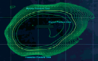
Figure 3. Narrow Spot Beam Coverage Analysis
Assisting operators to meet the needs of their customers, the CST takes as input the end customer’s requirements, including the number of terminals, type of equipment, terminal locations, and required data rates and availabilities. As the number of terminals increase so to do the variances in link performance.
Some terminals may be located in the center of a spot beam, others closer to the beam’s edge. In some cases, a terminal may be operating in a darker area between adjacent beams. Terminals may be located in areas with more significant weather effects, others in drier climates.
Although covered by the same spot beam, terminals may be located in areas within the beam that are subject to higher internal-interference caused by a side lobe of a near-by beam reusing the same frequency. The CST models all of these effects to help determine what can be expected as the “nominal” performance for the customer. Based on this, providers and resellers can set their customer service level agreements and committed and peak information rates.
Sizing the service plan for one customer is one aspect of the CST. A second and equally important aspect is combining multiple service plans into a group service plan to maximize the usage of shared capacity. By combining the service plans of multiple customers, the providers and resellers are able to take advantage of fluctuations and differences in the traffic profiles of different types of users.
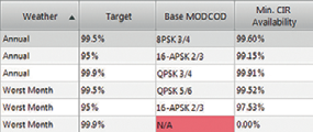
Figure 4. ACM Analysis for Annual and Worst Month Weather
For example, residential users tend to use more data in the evenings, while enterprise users tend to use more data in the mornings. By being able to combine and evaluate alternate group service plan designs, the SED CST allows service providers and their resellers to maximize the efficiency of their assigned capacity.
To aid in the longer-term aspects of capacity planning, SED provides a Capacity Planning Tool (CPT) that allows service providers and network operators to manage and plan the use of their transponder capacity over time. The CPT tracks the capacity of each channel on each beam in the system.
As the satellite payload is reconfigured the CPT can adapt to the changes. Usage is tracked either as a managed service plan using group service plans or as a power/bandwidth lease of a portion of a channel. As group service plans and leases transition through their lifecycle, the CPT manages them from time of inception, through provisioning, to implementation on the network.
When considering adding a new service plan or lease for a future period of service, the CPT is used to evaluate the viability of the service. If sufficient capacity is available then the service can be committed. If there is not sufficient capacity, the CPT will highlight the time periods and beams in which capacity is exceeded. The CPT also has the capability to integrate with the network hub in order to collect and analyze statistics on service plan utilization and congestion.
Intermodulation Considerations @ Ka-band
Intermodulation considerations are especially important for Ka-band transponders. Ka-band transponders have a much wider bandwidth than the traditional C-band transponders of 36 MHz and Ku-band transponders of 54 MHz. In the extreme case, Ka-band transponders can be as large at 1 GHz.
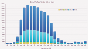
Figure 5. Diurnal Symbol Rate per coverage beam
To utilize these larger bandwidths, many of these transponders will operate in a multi-carrier configuration and will have to contend with intermodulation effects. Certainly, some systems will use a large TDMA forward carrier, but even with those systems, the return links generally deploy some form of in-route carrier compositions to meet the diversity of the terminal population.
With today’s leading edge modem technology, such as DVB-S2 and the recent S2X extensions, higher modulation schemes (64/128/256APSK) and tighter roll-offs (5 percent) are being used. These higher modulations schemes are susceptible to degradations caused by the satellite transponder nonlinearity and filtering impacts, and therefore increase the need for better management of intermodulation effects.
SED has developed high-performance sophisticated intermodulation analysis software to aid satellite operators and service providers to accurately model and manage the intermodulation characteristics of their satellite transponders. Using a time-domain implementation approach combined with a high-performance FFT library, SED’s intermodulation analysis engine provides highly accurate estimates of intermodulation noise while running almost interactively. The engine models carrier waveforms, thermal noise, and interference noise present at the input to the satellite receive chain.
Multiple planning modes also exist to help operators plan for a partially loaded transponder. Using simulated carriers in addition to actual carriers, the tool is able to help the operator estimate the impact of intermodulation noise at a full transponder load and correspondingly plan for an ideal operational point. This allows links to be designed once and then provisioned for longer durations
of operation.
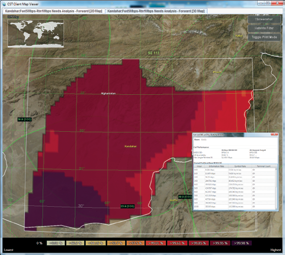
Figure 6. CIR Availability Analysis for a Region Supporting Mobile Terminals
Mobility, Military + Movable Beams
Having small terminal sizes, high data rates and narrow beams with concentrated power, Ka-band satellite systems are also well suited for mobility and military applications. Mobile applications of all types in both commercial and military spaces benefit from smaller, more efficient terminals.
However, as spot beams are typically very narrow and terminal routes and locations are varied, terminals will often transition across beams and in some cases satellites. For applications, such as military or emergency response, the satellite payload is often equipped with steerable antennas that allow additional spot beams to be positioned at specific locations. Being able to effectively plan the satellite beam coverage and capacity for mobile and military terminals can be just as challenging as operating a consumer broadband system over fixed spots. Beams move, terminals move, and performance varies by location. (Please see Figure 8 on the following page.)
SED’s capacity sizing and planning tools support mobile terminals and movable beams. Terminal movement can be specified as routes defined with way points, as a region of possible location, or as a group of beams.
The CST will analyze the routes and/or regions to determine the best beam coverage and corresponding channel capacity. Link performance, along with terminal counts and contention ratios, are used to aid the operator in developing a tailored service plan for a specific fleet of mobile terminals that provides continual service across the coverage area. Beams that can be repositioned via steerable antennas are also supported.
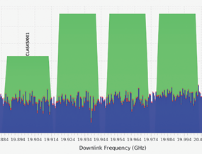
Figure 7. Visualization of Intermodulation Noise Spectra
Using the CPT, new beam positions for steerable satellite antennas can be considered and analyzed. Beams need to be repositioned with consideration of many aspects including intra-beam interference, gateway isolation, and regulatory and coordination constraints on geographical use of spectrum. These are all functions supported by SED’s capacity planning tools.
Maximizing the efficiency of high-throughput Ka- spot beam satellite systems demands new and innovative management and planning tools. Whether service is delivered through a closed network or over raw capacity, for commercial or military applications, SED Systems has the capacity planning and management software to provide flexible and cost-effective solutions for network operators, service providers and value added resellers.
SED Systems provides software systems, tools, and services to assist satellite operators, service providers, and network operators to efficiently and effectively plan and manage the capacity and services of their Ka-band satellite systems. Ranging from sophisticated capacity management systems, advanced link budget tools, capacity sizing and planning tools, and payload configuration tools, SED has the capability to deliver a solution to meet your requirements.
By leveraging existing software components and products, SED delivers tailored software to meet the specifics of your technical and operational environments. Whether you are operating a managed network, leasing raw transponder capacity, or optimizing your transponder loading and payload configurations, SED has the solutions to meet your capacity planning and management needs.
Russ is the Business Manager of Satellite Communications Planning and Management Systems at SED Systems. He is responsible for leading the strategy, growth and direction of the company’s Capacity Planning and Resource Management Systems and Services.
Russ has 20 years experience in the satellite communications industry designing and delivering systems for satellite operators and service providers. Russ directs and leads teams of engineers and software developers to deliver and support a wide range of solutions from highly-available ground segment systems to operational and engineering systems and toolsets.
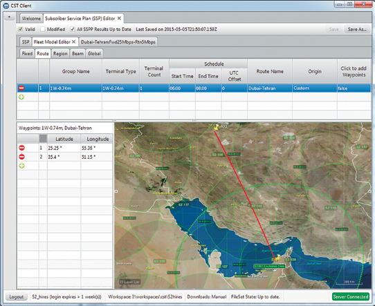
Figure 8. Fleet Editor: Planning of an Aircraft Route between
Dubai and Tehran