Less than 20 years ago, broadband Internet to the home first became a reality, thanks to the introduction of DSL technologies that enabled twisted copper pair to carry traffic at speeds above 1Mb/sec.
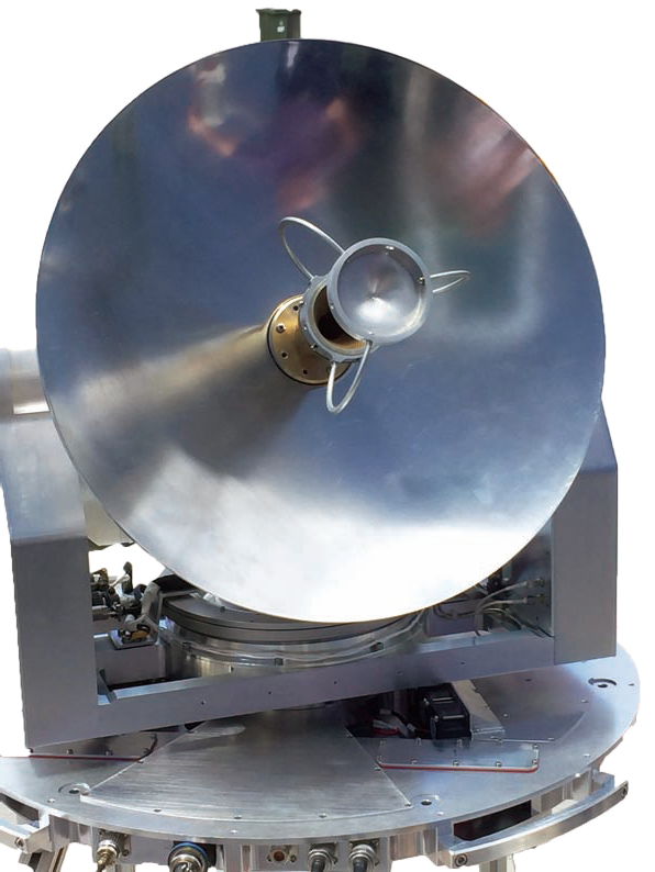
Figure 1. EM Solutions Ka-band militarized SATCOM-On-The-Move (SOTM) terminal with integrated closed-loop tracking.
Less than ten years ago, Internet access over a mobile phone became a relatively painless exercise. It is only today that 4G cellular networks and modern mobile phones are offering the same experience to the mobile user as is possible from wired or fiber connections in the home or office. Multimedia calls can be made to and from any country in the world, wherever appropriate 4G or WiFi infrastructure exists.
It is natural, then, to consider whether the user satellite communication (SATCOM) experience will ever be similar. Satellite “sleeves” are commercially available that transform an iPhone into a mobile satellite terminal. While these do offer true “use anywhere” experiences to a person in the two-thirds of the globe covered by the relevant satellite system, their data rates are measured in tens of kbits per second. However, broadband SATCOM requires higher frequency bands, and consequently antennas with higher directivity. This means that any sleeve would need to be repointed toward the satellite as it moves. For a mobile user, this requires constant adjustments to within a degree or two, either mechanically or electronically. As for automatically roaming between networks in the event of outages or lack of coverage? Not yet!
For a variety of reasons—not the least of which is the physics of limited signal/noise ratio—SATCOM can never match the multimedia experience offered to the mobile cellular user. Although SATCOM has one major advantage—fixed terrestrial infrastructure for backhaul to a central office is not required, so such services are available anywhere on Earth that the satellite beam covers—broadband roaming for a mobile satellite user still remains in the distance.
4G SATCOM Requirements: Bandwidth Anywhere On-The-Move
A core requirement for SATCOM to approach 4G in performance is to achieve robust, reliable, broadband communications under all common motion conditions, with assured availability and redundancy, even when one particular satellite is unavailable, for instance due to an outage, congestion, or weather-related fading.
The first of these requirements is to achieve a high data rate. Although this is now commonplace with a terminal in a single frequency band, this is not so easy as other requirements are added. For mission critical operation, a fixed frequency band may not always be available, due to congestion or environmental effects such as rain fade. All frequencies that support broadband requirements, such as X-, Ku-, and Ka-band, should ideally be available for use in these instances. This usually necessitates roaming between satellites and potentially different operators and requires more than a commercial consideration between different satellite operators—a multi-band terminal is also required.

A second requirement is support for mobility. In the higher frequency bands, which are most capable of supporting high data rates, antennas with reasonable gain will have narrow beamwidths and require pointing toward the satellite. Inaccurate pointing leads to loss in the link budget as well as poor performance and can result in unacceptable interference to users accessing other satellites. Off-road terrain, in particular, can be unique not only for violent motion, but also for susceptibility to path interference from overhead foliage or man-made structures. Recovery after such blocking is an important consideration.
A 4G cellphone user is rarely affected by either, as the lower frequency bands in which cellular systems operate do not require direct line of sight, and are able to achieve high data rates through clever re-use of frequency and multiple antennas that have relatively large beamwidths. Yet the same constraints pose serious challenges for SATCOM—any solution needs to acquire the correct satellite, remain pointing no mater the motion profile, and recover quickly from blockages, all with high gain, high directivity antennas. The system size, profile, and weight will also enter the design equation, given that the terminal may be used on a vehicle, plane, train, or ship.
Terminal Design
EM Solutions is making a start on its roadmap toward 4G-like SATCOM terminal performance capability. The company is currently developing a terminal capability that supports simultaneous military Ka-band and military X-band operation as well as automatic fallback to commercial Ka-band, all in a single terminal. Electronically switchable operation to Ku-band follows on the product roadmap. This will go further to match the ability of current 4G phones to adjust their settings, including frequency, to those of the environment and available network.
The technology to electronically switch between X-, Ku-, and Ka-bands is complex in terms of antenna, feed, and electronics design, particularly to avoid a brute-force approach of just combining three parallel systems into a single system. Using a single parabolic reflector that provides high antenna gain across all frequency bands, we have developed a single X- and Ka-band feed, and a single X- and Ka-band solution for the BUC, still maintaining excellent phase noise and monopulse pointing for accuracy. The Ku-band feed that comes later on our roadmap will comprise a separate parallel structure that uses the same reflector and will be electronically switched in to the correct focal point on the reflector when that band is activated.
The terminal senses the signal to achieve the correct polarization, whatever the band, and points the terminal accurately, using closed-loop monopulse tracking of the satellite beacon to minimize the pointing error and maintain a lock on the satellite while on-the-move. Using a parabolic reflector maintains signal and also reduces the transmit sidelobe signal density to avoid interference with adjacent satellites, whatever the frequency.
We are achieving these features by modifying EM Solutions’ existing Ka- and Ku-band on-the-move terminal designs (Figures 1 + 2) and adding the following capabilities:
• A light-weight sub 1-meter antenna reflector and integrated waveguide feed capable of operating simultaneously at X-band, commercial Ka-band, and military Ka-band frequencies without
physical intervention
• A diplexer structure to combine RF signals from a single X-band / Ka-multiband block up converter (BUC) and into multiple low noise block down-converters (LNBs) fitted to enable simultaneous transmission and instantaneous switching between any of the selected communications bands without manual intervention
• Software to manage either manual or automatic fall-back to alternate bands, provide network element management functionality for plug and play capability, and to provide appropriate layer 2- and 3- functionality where necessary for self-healing Universal stabilization to the most severe motion conditions through a monopulse pointing technique, so the terminal can be used either on land or at sea Integrating all X-and Ka-band electronics within the radome, avoiding the need for expensive and lossy waveguide runs to external equipment racks
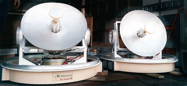
Figure 2. Existing EM Solutions Ku-band SOTM terminals showing the parabolic reflector antenna and the monopulse feed.
An important design consideration is to achieve the simplest solution possible. Although three separate X-, Ku-, and Ka-band on-the-move terminals could conceivably be integrated into a single solution, this would be bulky, expensive, and prone to failure.
Creating a single X-/Ka-band feed, including monopulse pointing for closed-loop tracking of the terminal, is one example where clever design has enabled a simpler and more integrated system to be created within a single structure.
A second example of innovation is in the RF transmitter (block upconverter) electronics. As a starting point, EM Solutions’ current Ka-band BUC covers 28 to 31 GHz across military and commercial Ka-bands and remains small enough to qualify as an EM Solutions nanoBUC product.
Rather than being designed as a parallel combination of three traditional BUCs with heavy filtering and potentially in-band local oscillators operating at 27GHz, 28 GHz, and 29GHz respectively, the company adopted a dual conversion architecture in the design to achieve multi-band coverage. Dual up-conversion involves translating the input IF frequency from the modem to a secondary IF frequency before further up-converting the block of frequencies around the IF to the desired band.

The benefit of this approach at Ka-band is that the LO of the final mixer can be well separated in frequency from the desired RF signal, thereby allowing the output filter to operate over a 3 GHz bandwidth (at Ka-band) while still rejecting any leakage at the final LO frequency. With this architecture, there is only need for one Ka-band waveguide filter and no mechanical microwave switches, as would be required in a brute-force triple BUC combination.
There are three main concerns when implementing a dual stage up-converter: spurious signals, gain flatness and phase noise. The first of these can be overcome by careful frequency planning and filtering at appropriate stages; the second by maintaining excellent return loss throughout the various stages; and the third by careful design of the main frequency synthesizer to operate across a broad frequency range. This required the first LO to operate around 5.5 GHz and the final LO to operate around 22.5 GHz, as shown in Figure 3 on the previous page.
Importantly in the current context, this BUC allows the X-band frequencies to be generated directly at the output of the first upconversion stage by appropriate tuning of the first LO and appropriate post-amplification. This means that a single BUC can be used to electronically switch between X- and Ka-band without adding unnecessary complexity, cost, and weight into the terminal. Coincidentally, it also parallels the approach taken in the design of current 4G mobile phones.
SATCOMs And 4G
Broadband on-the-move SATCOM terminals of the type described in this article are able to offer true mobility and high data throughputs to military users and first responders, even under the most demanding mobility requirements. Automatic switching between satellites and frequency bands is made possible by end-user equipment that can automatically detect loss of signal in the favored band, and respond by switching bands and satellites automatically and without user intervention if desired.
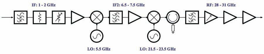
Figure 3. EM Solutions BUC architecture for realizing selectable output bands
The system under development uses a single shaped parabolic reflector and horn with a combined waveguide feed for both transmit and receive signals at both X-band and multiple Ka-bands, to automatically switch between bands depending on prevailing conditions. Compared with the current class of existing terminals, the benefits of this terminal will include:
• Fully transportable and operational on-the-move capability with unparalleled satellite tracking capability in three bands across all ranges and types of motion (land, sea, air)
• Support for broadband communications (data rates up to several Mbps) without using excessive satellite transponder resources consumed by a very small terminal, but with the option to reduce footprint and weight if necessary by changing reflector size
• Fall-back to a fully integrated commercial capacity (with built-in modem) in the event of failure or congestion of the primary network
• Network survivability with assured communications in a contested environment
• Rapid and automatic self-healing in the event of rain fade or other link outage
• Configurability for a range of platforms to suit either a small or medium vehicle or vessel, with simplified field repair and cost optimization
Although such a system is still a long way from a hand-held 4G cellphone because of its weight and size, please recall the size and weight of the first mobile phones 30 years ago. EM Solutions and others in the industry are developing new antenna and system technologies that share many of the communications’ features offered by a 4G phone and they will help pave the way for increased uptake of SATCOM.
Additional information regarding EM Solutions may be viewed at http://www.emsolutions.com.au/
Editor's note: “EM Solutions wishes to acknowledge that the research and development of the heat exchanger and EMI/EMC technology of the terminal in Figure 1 were funded through a project supported by NICT Japan.”

Rowan Gilmore is CEO of EM Solutions Pty Ltd, an Australian designer and manufacturer of advanced microwave modules and systems for satellite and wireless broadband communications networks.
He has worked extensively in the ICT industry, and was formerly based in Sydney, Atlanta, London and finally Geneva as Vice President of Network Services (Europe) for the airline IT company SITA, now France Telecom’s Orange subsidiary. He was previously Manager of Advanced Global Networks in Telstra’s International Business Unit. Prior roles have been with Schlumberger as both a General Field Engineer on various assignments throughout Asia, and as an R&D Manager in Houston, Texas.
He is an engineering graduate and winner of the University Medal from the University of Queensland, and earned his Doctor of Science degree from Washington University in St. Louis in the U.S. He currently holds Adjunct Professorships in both the School of Business and the School of Information Technology and Electrical Engineering at the University of Queensland, Australia.