
Gallium Nitride (GaN) amplifier technology is finding a place in satellite ground terminals alongside established GaAs solid state BUCs and tube-based HPAs. Manufacturers are implementing the technology — to varying degrees of effectiveness. How to know if it is the correct fit for your deployment — or just one more buzzword?

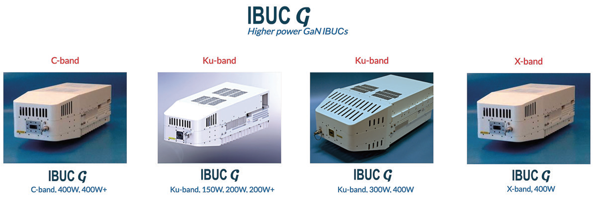
200W Ku-band IBUCG
1— High Power Density
Compared with GaAs (Gallium Arsenide), GaN amplifier devices deliver greater gain and are capable of producing higher output power per device. What this means for the RF designer is that they can obtain the target output power with fewer devices.
Combining losses and costs impose practical and economic limits to the number of devices that can be used in a single amplifier. This is what has constrained manufacturers from deploying higher power GaAs BUCs and SSPAs.
What this should mean for the uplink terminal buyer is greater output power in a smaller, lighter package — perhaps at a reduced investment. Sounds good, right? More power for less. But is the technology delivering on its promise?
Read on...
There likely are more, but two applications lend themselves to these characteristics:
• A small, lightweight product for high mobility applications such as manpack or flyaway terminals.
• Higher power BUCs/SSPAs as a reliable alternative to Traveling Wave Tube Amplifiers (TWTAs).
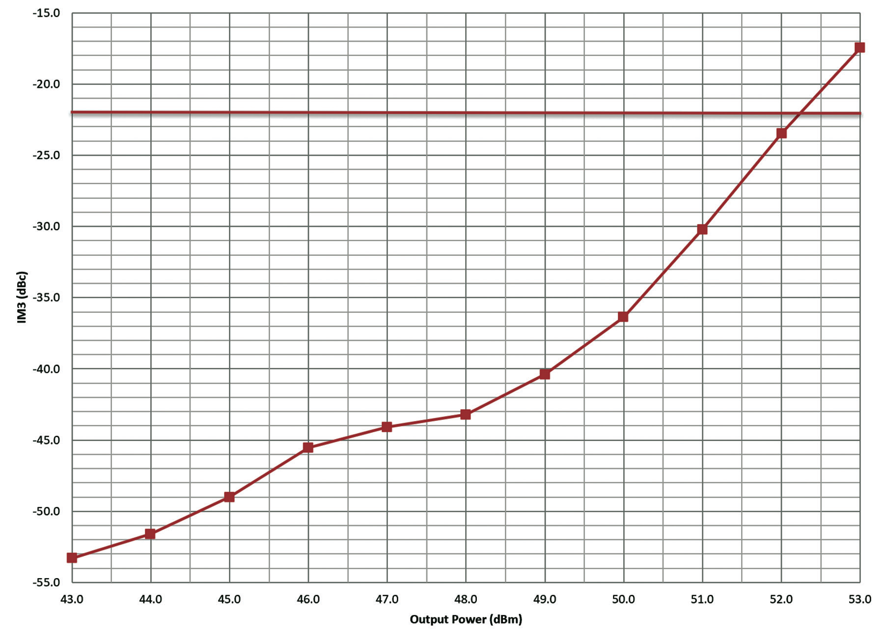 Chart 1. IMD3 Plot of a GaAs 200W C-band IBUCR.
 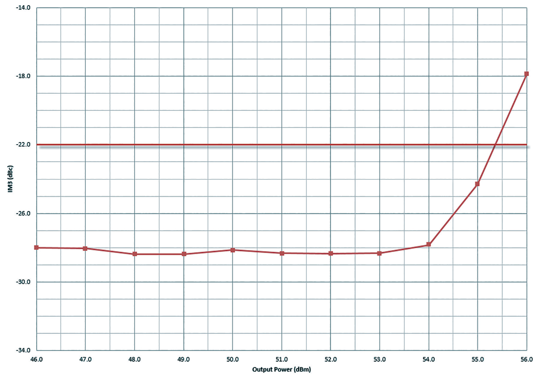 Chart 2. IMD3 Plot of a GaN 400W C-band IBUCG.
Tech Delivering on its Promise
The higher power density presents an issue for the microwave designer and therefore for the user. Higher power in a smaller space means more heat. GaN devices themselves operate at a higher temperature than other solid-state devices. They can tolerate it. However, other devices must be protected from that heat, and it must be removed from the amplifier.
Heat is the major contributor to shortening the life of the unit. There is a tension in which the engineer designing the amplifier wants to maximize surface area to remove heat while the user wants the smallest surface area for mobility and ease of antenna mounting.

A little-publicized characteristic of GaN devices is their tendency to self-destruct when driven beyond saturation. It is necessary to design protection into the gain control circuit so that the amplifier cannot be overdriven and fail. More power is a real advantage. But it must be handled with care.
2 — Understanding Output Power Can Be Tricky
With GaAs SSPAs and BUCs, the P1 dB compression point is a well-understood single measurement that provides a point for rating output power. Sure, manufacturers play with measuring only at room temperature or stating saturated power. But the customer can usually see through that in order to make a valid comparison.
With GaN, that’s not so easy. Due to the inherent non-linearity of GaN devices, the P1 dB compression point is 5 to 6 dB below the saturated power of the amplifier — this means it is not a useful measurement of output power.
Unfortunately, manufacturers began stating the rated output power of their BUCs at the saturated power level (PSat). It is a true point of measurement but it’s not a valid statement of the useful output power of the amplifier.
This is where it gets tricky. Take a deep breath. It is somewhat like the much more mature TWTA amplifier ratings where the data sheet says 750W, but everyone in the industry knows that value is only the tube PSat rating. There are losses to the waveguide flange and 5 to 7 dB of back-off required to get the unit operating in the linear range. The 750W TWTA amplifier delivers 200 to 350W, depending on the implementation.
There is a substantial difference in the implementation of GaN among manufacturers. That difference determines whether the purchase is a good one or a career-endangering mistake.
As PSat is not a meaningful indicator of usable output power, the industry needed a better method for stating usable output power. For better or for worse, the industry has adopted the MIL-STD-188-164B definition as a method for comparing the useful output power of two GaN amplifiers.
The definition has two components — spectral regrowth <-30 dBc and third order Intermodulation Distortion (IMD3) of <-22 dBc for two carriers. The two components of the definition do not line up with any specific commercial satellite. Some operators allow higher spectral regrowth and others demand better IMD3 performance. It does not cover the full range of applications — but is far more meaningful than simply noting the PSat rating. For more on the exceptions, keep reading.
It is tempting at this point to present a table showing the broad variation between PSat and PLinear among suppliers. In some cases, the PSat is the same, but the difference in usable power is 3 dB. How can two data sheets call the BUC the same thing and one makes twice the power of the other? It is in the implementation of the technology.
Another issue is that the non-linear power transfer curve of a GaN amplifier is not fully compatible with the algorithms for adaptive modulation coding that several modem manufacturers use. This can result in unexpected, undesirable results. If the GaN BUC offers an Automatic Gain Control (AGC), that can compensate for the non-linear gain issue.
 Terrasat IBUC G and IBUC 2G models are carefully designed for minimal back off— that means more usable power for your investment.
3 — Reduced Power Consumption
When the first BUCs/SSPAs were being launched with GaN devices, one of the talking points was that the technology would cut AC power requirements significantly at hub sites. However, comparing data sheets with equivalent power GaAs models, the difference was in single digits.
The newer generation of GaN packages supplied by the device manufacturers are delivering large improvements in power consumption. In some cases, the reduction is nearing 40 percent. Coupled with energy-saving techniques such as Eco-Mode in IBUC redundancy systems, where the standby amplifier is shut down until needed, power consumption may be reduced by as much as 65 percent. The knock-on impact for UPS and generator sizing can lead to real savings.

4 — Multicarrier Limitations
Given the higher solid-state output power of GaN amplifiers, they are perfect alternatives to TWTA amplifiers, right? Well, perhaps...
All technologies have their strengths and limitations. With GaN devices, limitations can become evident in operations using more than one carrier. This is not to say that it cannot be used with multiple carriers. But GaN performs differently than GaAs or TWTA amplifiers with respect to multi-carrier operation. There are two situations where this limitation should be respected.
Power Play
First, with a GaAs amplifier there is a fairly linear and continuous IMD3 improvement with output power back-off. Below is an IMD3 plot for a 200W C IBUCR GaAs amplifier. (The red line is the -22 dBc IMD3 part of the MIL-STD linearity definition).
It is evident from the plot in Chart 1 to the right that IMD3 with a GaAs amplifier decreases rapidly and in a fairly strong correlation to a reduction in output power (back-off).
With a GaN unit, there is a different result — see the IMD3 plot below of a 400W C-band IBUCG GaN unit. Things start out fine, but the curve quickly starts to flatten. At about 2 dB of output power back-off, IMD3 hits a “floor.” It doesn’t get any better. This is a characteristic of GaN devices that cannot be overcome (see Chart 2 to the right).
What this means is that there may be a limitation to the quantity of carriers that can accommodated. The key factor in amplifier design is minimizing the amount of output power back-off needed to achieve PLinear. If the BUC needs 3-4 dB of back-off to the PLin point, there may not be enough left to accommodate back-off required for multiple carriers.
Memory Issues
The second limitation, called the “memory effect” only shows up in situations with widely separated carriers. By the MIL-STD definition, manufacturers specify IMD at a 5 MHz carrier spacing. When carrier spacing is increased, the IMD level also increases, potentially causing interference to other carriers. The effect varies by frequency band and power level. Manufacturers are taking steps to mitigate the effects, and newer devices are showing improvements. But it is a characteristic inherent to the GaN device and a factor to take into consideration.
5 — Reduced Cost (most of the time)
With all the talk of trickiness about power level measurement and limitations for multiple carrier operation, it’s time for something positive. Good news for the industry — GaN technology is having a positive impact on prices. Since it enables simpler combining and smaller enclosures, that leads to materials cost reductions.
The performance and delicacy of the early devices for satellite applications made implementing GaN an expensive development exercise. With the improvements in device performance and robustness, the cost of manufacturing has become more predictable. In many cases, GaN is bringing the cost of higher power BUCs down in terms of dollars per watt of usable power. It may not hold true at all power levels and for certain applications. This is a trend in the correct direction — and certainly one to watch.
www.terrasatinc.com