
The recently launched multi-spot beam High Throughput Satellite (HTS) systems that are capable of delivering several tens to more than 100 Gbps throughput, reveal to the users as well as the satellite operators an opportunity to significantly lower the cost of the satellite data service that has been dominated by the wide beam Fixed Satellite Service (FSS) satellites.

To accommodate even higher data-intensive services in the future and compete with the ground broadband providers in some under-served markets, a much more competitive and advanced HTS system should be envisaged. A system that can support at least one magnitude higher throughput and is fully flexible in relocating the payload re-sources.
In the roadmap to the future HTS, one of the most critical elements lies in the output section design, which handles the high power microwave signals. The output performance is directly related to the spacecraft sizing, spectrum efficiency and, hence, the total throughput that can be harvested.
This article describes and compares the feasible output section technologies and implementation configurations that can practically improve the future HTS’ throughput and flexibilities.
Technologies for the Future HTS Output Section
An HTS repeater system consists of the input section and the output section. The input section is mainly the low power payload of the HTS, which handles the received uplink signal from the gateway forward beams and the user return beams.
The input section picks up the RF carriers from the receiving (Rx) antenna, amplifies them, converts the frequency and then routes them to the output section. The output section is mainly the high power payload of the HTS, which the power amplifies the signals routed from the input section, and then feeds them to the designated downlink beams by the transmitting (Tx) antenna. The HTS antenna system receives the input signal and transmits the output signal of the same beam simultaneously from the same cluster feed.
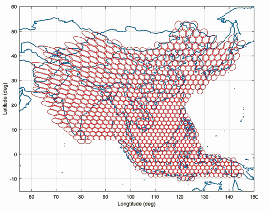
Figure 1. A future multi-beam HTS layout over East Asia
for > 1Tbps throughput.
A future Tbps-class HTS that covers East Asia is illustrated in Figure 1 to the right. To make such high throughput possible, the number of beams, as well as the beam capacity of the HTS itself, must be significantly increased. Since the beginning of HTS, most of the industry’s efforts focused on feed cluster integration and RF payload performance improvement. On the input section, the noise figure is reduced to as low as possible, while on the output section, the RF output power is augmented to as high as possible. This results in a high overall link carrier-to-noise ratio, so the capacity of each beam and the whole satellite can
be enhanced.
Unfortunately, the more challenging problem now faced is that not all of the designed capacity could be consumed. With more HTS joining the competition, simply increasing the throughput for a future HTS design may not be enough. What the HTS operators craved for is full flexibility in order to readily reassign the payload resource during the lifetime of the satellite.
On the input section, the flexibility can be realized by a digital channelizing processor (DCP). A typical onboard DCP is capable of the signal carrier’s digitization, segmentation, routing, reassembling and multi-casting between different beams, easily achieving the star, mesh and loopback net-work topologies as required.
Many useful functions, such as onboard carrier spectrum analysis, anti-uplink jamming, and gateway deployment ramp up, can also be achieved by DCP, bringing solid flexibility to the HTS operators.
Currently, the DCP begins to be more popular and is adopted by more and more HTS payload designs. This technology is still quickly evolving toward the future specifications of ultra-wide processing bandwidth (BW), lower DC power consumption and even higher processing speeds. The only limitation is, with just DCP, the beam throughput flexibility cannot be truly fulfilled without the design change on the output section.
A desirable “future-proof” HTS must possess the true throughput flexibilities, including:
1) Beam bandwidth (BW) adjustability
2) Beam power adjustability
3) Beam shape adjustability
With the use of DCP, the input BW adjustability can be achieved by the control of carrier BW, sharpness and regrowth levels. The band-limiting input multiplexer’s (IMUX) function can be taken by the digital processor, as is illustrated in Figure 2(a) and (b) on the following page. However, the beam absolute BW is still limited by the channel BW of the output multiplexer / de-multiplexer (OMUX).
Currently, most commercial HTS still adopt OMUX design (Figure 2(a), (b). This is because the conventional traveling-wave tube amplifier (TWTA) is still widely used for the microwave high power amplification.
The merits of a TWTA are the high output power, high power-added efficiency (PAE), high operating frequency and wide operating bandwidth. However, TWTA’s heavy mass, bulky profile and high DC power consumption features also virtually prevent the configuration of single beam per TWTA for an HTS with hundreds of spot beams.
 When multiple beams per TWTA have to be configured, carefully-designed OMUXs tailing to the TWTA output ports must be used to channelize and route the amplified microwave signals to the designated downlink beams. Once the OMUXs are manufactured and installed, the output beam BW adjustability is then constrained.
The corresponding beam power adjustability would also be limited due to the multi-beam per TWTA configuration. Even though the recently-proposed tunable output filters may help the beam’s BW flexibility, their complex tuning mechanisms cannot guarantee the reliability offered by the conventional fixed OMUXs.
To realize the full flexibility of the output section, Monolithic Microwave Integrated Circuit (MMIC) based transmit/receive (T/R) modules have to be used and integrated with the HTS antenna feeds. Each module contains the MMIC low noise amplifier (LNA) and the MMIC solid-state power amplifier (SSPA) with significantly reduced profile, mass and DC power consumptions compared to their conventional discrete counterparts in the input and output sections.
As shown in Figure 2(c) below right, the LNA and the SSPA in the T/R module immediately connect to the Rx and Tx ports of each feed, introducing much lowered cable loss and cable mass than those in a traditional HTS. With the one T/R module per beam design, no fixed narrowband channelizing devices are needed throughout the signal path.

The frequency selectivity is solely driven by the DCP at the input, implying that each beam can occupy the whole available downlink spectrum without the fixed multi-color scheme used in a conventional HTS design. The beam traffic and inter-beam interferences can be optimized by the carrier frequency and BW allocations managed by the ground system with the aid of the onboard DCP, and, thus, the beam capacity and BW flexibility can be greatly improved.
The MMIC-based active T/R module antenna feed is also a cost-effective output-end solution to the future HTS, where extremely narrow spot beams of high frequencies (e.g., in Ka-band) are massively deployed. Thanks to the high antenna gain of the narrow spot beam, the downlink output power requirement on the onboard SSPA can be relaxed, which, in turn, reduces the cost of the MMIC module.
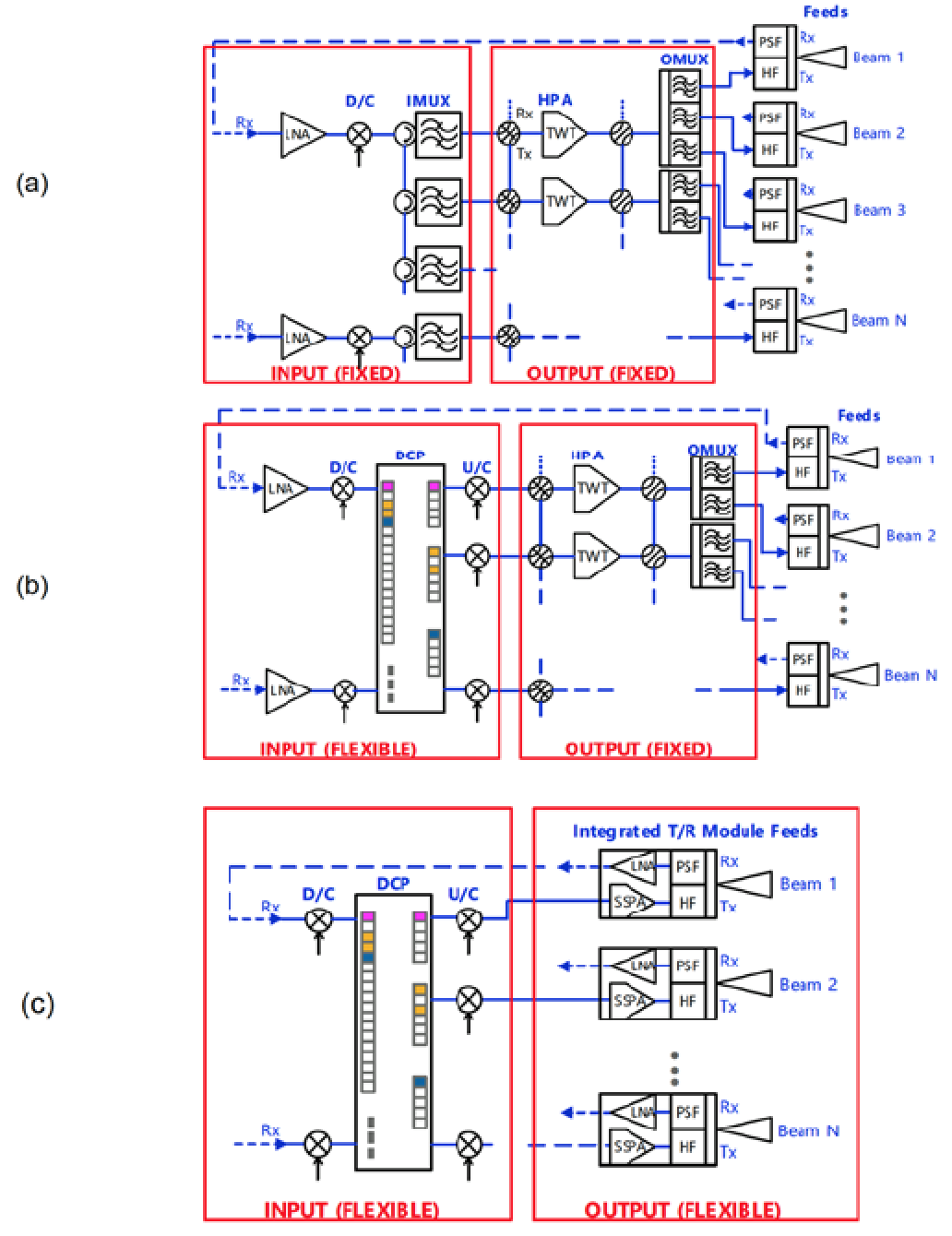
Figure 2. HTS payload evolution illustration: a). conventional fixed input/output sections, b). flexible input section with DCP, and c) flexible input/output sections with DCP and integrated T/R module cluster feeds antenna.
Traditionally, such active T/R antenna feeds are more common in the low frequency (e.g., L- and S-band) satellite payloads that incorporate Gallium Arsenide (GaAs) semiconductors. With many years’ research and development in the industry, the Gallium-Nitride (GaN) based MMICs have been gradually adopted in the Ku- and Ka-band satellite communication payloads, as well. The GaN-based LNA boasts of a high robustness and higher linearity performance.
The wider band gap, higher operable junction temperature and higher electron mobility properties of GaN semiconductor make it more appropriate for the high frequency space-borne power amplifier than those by GaAs.
Moreover, the relatively higher output impedance of GaN amplifiers eases the matching network’s design, while the high drain voltage simplifies the DC/DC power supply net-work’s design, which all favor the integration and packaging of the MMIC for the HTS application.
The use of GaN MMIC also facilitates the miniaturization and integration of the active and the passive components, e.g., gain blocks, phase shifters, attenuators, mixers, oscillators and even switches and isolators that a repeater system required, onto the same microwave chip.
With the help of specialized software and hardware modules in the DCP, the MMIC-based active T/R array-feed antenna system can be easily configured to realize digital beamforming (DBF).
The DBF function is the prerequisite of the advanced beam flexibilities, such as electrical beam-steering and beam shape adjustment, which are beneficial to the future HTS business when high resolution conformal coverage contours are required.
The MMIC-based active T/R module configuration simplifies the feed network design, not to mention the mass saving by the T/R module itself. Then the complex waveguide feed networks existing in a traditional HTS can now be replaced by a straightforward design with much lighter cables.
The corresponding path loss saving is translated into a much better noise figure at the input section and a higher downlink power at the output section. The redundancy design is also made straightforward thanks to the simplified network and the smaller beams used.
If the DBF function is equipped, any single beam failure can be compensated by beam-forming and would only bring graceful degradation on the coverage instead of leaving a black hole as in a traditional HTS system.
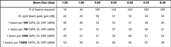
Table 1 HTS spot beam downlink EIRP trade with beam sizes and HPAs of different output power levels.
Output Section Performance Comparison
This section compares MMIC-based HTS output design performance with the conventional TWTA-based HTS design.
Assuming a fixed coverage area, such as China, illuminated by the beam layouts of different beam sizes, the corresponding number of beams and the downlink spot beam gains are shown in the first two rows of Table 1 below. The downlink EIRP of the spot beams with 5W, 7W, 10W SSPAs as well as 150W TWTA cases are also shown in Table 1 above.
The SSPA operation assumes 2 dB OBO and adopts 1 beam per amplifier configuration, while the TWTA operation assumes 3 dB OBO and adopts 2 beams per amplifier configuration. The beam antenna gain makes the greater portion of the EIRP when spot beam size decreases.
Even the TWTA case always gives a higher downlink EIRP than the SSPA cases — the overall link performance would not be limited only by the beam EIRPs, the other factors such as the inter-beam interference, inter-modulation interference, adjacent satellite interference, uplink carrier to noise ratio, and so on.
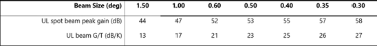
Table 2. HTS spot beam uplink G/T change with beam sizes.
The overall link performance can also become the bottleneck when the beam size shrinks, leaving the high downlink EIRP of marginal help to the throughput.
With the narrower spot beams employed in the future HTS, the beam uplink G/T will also increase, which benefits the uplink performance and thus the total throughput of the HTS. The typical Ka-band beam peak G/T values of different beam sizes are listed in Table 2 above for reference on the following page.
The HTS throughputs and the estimated DC power consumptions are compared in Figure 3 below using the number of beams and beam sizes shown in Table 1, while the BW per user beam is assumed to be 250 MHz on the forward link. It can easily be found when the beam size is larger than 0.5 degrees, the TWTA-based solution provides more throughputs with the realizable HPA DC power levels (<20 kW).
However, when the beam size continues to reduce, the TWTA DC power consumption would be too high to be acceptable on a GEO satellite platform.
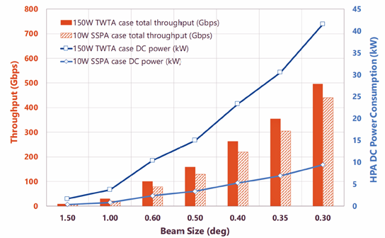
Figure 3 Throughput and DC power consumption trend for an HTS covering the same area with different beam sizes and HPA types.
On the other hand, the MMIC-SSPA based solution provides the comparable throughput with a much lowered DC power consumption, even when the total throughput reaches 400 Gbps (399 x 0.3 degree spot beams).
In this article, Figure 3 to the left only compares the DC power with the throughputs. However, other key physical parameters of a satellite, such as the payload mass, HPA thermal dissipation, etc., can also be compared, only with the same conclusion reached that the MMIC-based technology would be more competitive and cost-effective in the output section design of a future HTS.
If taking 60 dBW EIRP as the line of demarcation of a good downlink design, then the best trades between HTS beam size and SSPA power level are: 5W for 0.3 degrees, 7W for 0.35 degrees and 10W for 0.4 degrees.
Resources
1. A. Le Pera, F. Forni, M. Grossi, M. Lucente, V. Palma, T. Rossi, M. Ruggieri, “Digital Transparent Processor for Satellite Telecommunication Services,” Proc. IEEE Aero. Conf. 2007,
March 2007.
2. D. Bell and B. Clebowicz, “Systems and Methods for Digital Processing of Satellite Communications Data,” US Patent, 7,542,716 B2, 2009.
3. G. Thomas, N. Jacquey, G. Huggins and P. Jung-Mougin, “Flexibility in High Throughput Satellites,” AIAA ICSSC 2016, Cleveland, USA 2016.
4. C. Kudsia, R. Cameron, and W.-C. Tang, “Innovations in microwave filters and multiplexing networks for communications satellite systems,” IEEE Trans. Microw. Theory Tech., vol. 40, no.6, pp. 1133-1149, June 1992.
5. C. Ernst, P. Angeletti and F. De Paolis, “Needs for Bandwidth Reconfigurable Filter Networks for Space Application,” AIAA ICSSC 2013, Florence, Italy 2013.
6. A. R. Barnes, A. Boetti, L. Marchand and J. Hopkins, “An Overview of Microwave Component Requirements for Future Space Applications,” Proc. Gallium Arsenide other Semicond. Appl. Symp., pp. 5-12, 2005.
7. E.M. Suijker, M. Rodenburg, J.A. Hoogland, M. van Heijingen, M. Seelmann-Eggebert, R. Quay, P. Bruckner, F.E. van Vliet, “Robust AIGaN/GaN Low Noise Amplifier MMICs for C- Ku- and Ka-band Space Applications,” CSIC, 2009.
8. J.-L. Muraro, G. Nicolas, D. M. Nhut, S. Forestier, S. Rochette, O. Vendier, D. Langrez, J.-L. Cazaux, M. Feudale, “GaN for Space Application: Almost Ready for Flight,” Int. J. Microw. Wireless Technol., vol. 2, no. 1, pp. 121-133, Apr. 2010.
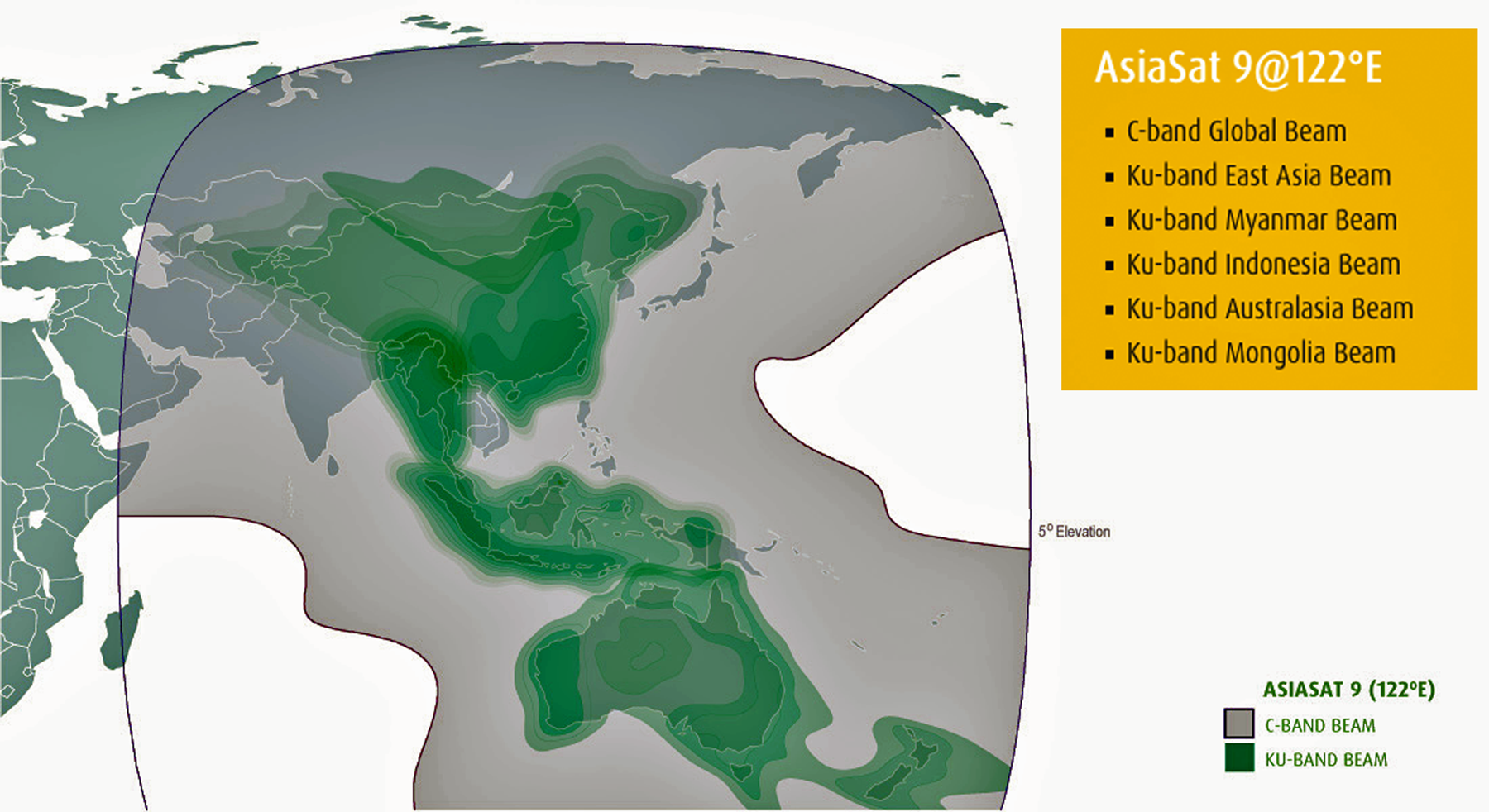
Launched on September 29, 2017, from Baikonur, Kazakhstan, AsiaSat-9 is AsiaSat’s next-generation satellite, which is planned to replace AsiaSat-4. This satellite is a Space Systems Loral (SSL) 1300 satellite and is equipped with multiple C, Ku and Ka-band payloads. AsiaSat 9 will provide additional capacity, enhanced power and coverage for DTH, video distribution, private networks and broadband services across APAC.