Gallium Nitride (GaN) FETs boast significant benefits over their Gallium Arsenide (GaAs) based counterparts. Higher efficiency, wider bandwidth, improved reliability and higher output powers are just some of their features. Their higher output impedance also means that it is easier to achieve broader bandwidths.
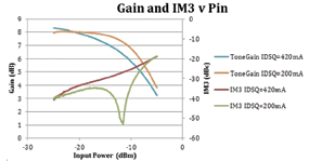
Figure 1. Ka-band GaN PA under different drive conditions.
GaN Power Amplifier (PA) Microwave Monolithic Integrated Circuits (MMICs) are finally available at Ka-band and are now generating a wave of new Block Upconverter (BUC) designs for use in satellite communication transmitters. Such designs seek to maximize the advantages of GaN devices by making more powerful and reliable units in smaller footprints.
Higher Linear Power
Traditionally, SATCOM based FETs (Field-Effect Transistor) and MMICs have operated in class-A. In class-A, the output FET is biased so that both the current and voltage are able to swing from rail to rail. This gives the best linear performance. However, the maximum theoretical efficiency of the output FET is only 50 percent. This efficiency only occurs at the maximum output power. Considering Ka-band FETs only produce about 7-8 dB gain per stage and that all these FETs run off the same input voltage, the total overall efficiency of a BUC (Block Up Converter) is less than 15 percent.
GaN FETs have been designed to operate closer to class-B or “deep AB.” That is, they operate with the gate voltage biased closer to the off condition so that the current is essentially clipped when the voltage reaches a peak. This mode of operation improves the efficiency but comes with some trade-offs.
The first is increased harmonic content. In class-A operation, the ideal FET produces no harmonic content when operating within its voltage limits. As the FET is moved from class-A through to class-B, it uses less DC power. However, the spectral content increases, which leads to higher harmonic and intermodulation distortion products. There is another point close to class-B where both the third and fifth harmonics reach a minimum. At this point, if a short circuit is applied to the second harmonics, then it is possible to produce an amplifier with higher efficiency and less harmonic output power.
Another downside of operating in class-AB is that Pout (Push Out) no longer increases linearily with Pin (Push In). In other words, the amplifier exhibits “soft” gain compression over a wide input power range. This effect is exacerbated in GaN PAs where the device characteristics add further to the slow gain roll-off. However, it is possible to bias the GaN device deep in class-AB such that the soft gain compression somewhat corrects itself.
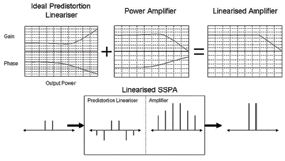
Figure 2. Equivalent ways of conceptualizing the operation of a predistortion linearizer: gain and phase correction (top); intermodulation injection (bottom)
Figure 1 (left column, bottom) shows a comparison of the gain response of a GaN MMIC biased in class AB (IDSQ=420mA) and deep class AB (IDSQ=200mA). As the curve shows, the gain versus power response for the latter case is much flatter. The harmonic content of the amplifier operating deeper in class-AB is also lower, as seen by the dip in the third-order intermodulation distortion (IM3) response.
Now, linear power is often defined as the total power in two tones when the IM3 products are -25 dBc relative to the total power, or -22dBc relative to the power in each tone individually. Using this definition, it can be seen from Figure 1 that a Ka-band GaN PA biased deep in class-AB will reach this linear power when the gain drops by 2dB with respect to the small signal gain. Also evident is that as the gain is higher and the IM3 products are the same, the achievable output power should also be higher than in “mild” class AB. Measuring the output with a power meter confirmed that it was actually about 1dB higher.
Such improvement by adjusting the bias suggests that further improvement may also be possible by introducing a predistortion linearizer. A predistortion linearizer can be modeled in one of two ways. One way is to think of the linearizer as correcting the power transfer curve, so ideally an amplifier should exhibit a linear power transfer function—the gain and phase should both remain constant until the amplifier hits its saturation point. An ideal predistortion linearizer would exhibit the opposite gain and phase response to the PA—overall, the responses cancel one another.
A second way of visualizing a predistortion linearizer is that it actually creates opposite-phase intermodulation products that mix with the intermodulation products of the main PA. Both of these concepts are presented in Figure 2 on the previous page.
One of the most common forms of predistortion in communication systems is to use digital techniques at baseband (Digital Predistortion). Using this technique, canceling the third- through to the seventh-order intermodulation distortion products by more than 30 dB at a particular power level is possible. However, this technique has several drawbacks and is not often used in SATCOM BUCs.
The first and most obvious reason is that it requires access to the baseband signal when it is being generated by the modem. This would mean that the BUC and SSPA (Solid State Power Amplifier) must also be characterized for operation with a particular baseband generator (modem). Also required would be that the IM3 products be largely monotonic with respect to the input power.
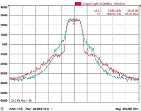
Figure 3. Comparison with the linearizer OFF (blue) and ON (red). (Modulation scheme is OQPSK, 2.048 MBit/s, 1/2 rate Viterbi)
Finally, the IM3 products suffer memory effects in the SSPA. That is, the PA responds slightly differently when abruptly changed from low-to-high power as it does when it changes from high-to-low. The digital predistorter is simply not fast enough to compensate for this effect.
The preferred option to linearize SATCOM BUCs is to use analog predistortion. These circuits generally work by driving an active element, such as a diode or transistor, into saturation and coupling the intermodulation products, at some predetermined phase, back onto the main signal path. Due to their inherit nature, analog circuits are able to respond much more rapidly to changes in power level and are not as susceptible to memory effects.
EM Solutions has developed an analog linearizer that specifically targets GaN PAs and incorporates it into their latest generation of Ka-band upconverters. Figure 3 below shows a comparison of the spectral regrowth with the GaN PA biased at 420 mA and operating 2dB below saturated output power (blue), and the PA with the same bias and output power but with EM Solutions’ linearizer turned ON (red).
As can be determined from the plot, the spectral regrowth in the adjacent channel has been improved by more than 10 dB. Although the spectral regrowth in the alternate (next adjacent) channel is worse, the transmit spectral masks are usually such that the benefits of increased output power with lower adjacent channel interference warrants use of the linearizer.
Compact Designs
Another benefit of GaN based solutions is the resulting smaller form factor. One of the limiting factors in SSPA designs is the ability to effectively remove heat from the devices. However, as GaN is more efficient than GaAs, it is possible to make higher power units in smaller form factors.
For example, EM Solutions’ first generation Ka-band nanoBUC was able to deliver 16W saturated output power in the smallest form factor in the market. Using GaN, EM Solutions’ Ka-band multiband nanoBUC can achieve 25W saturated power in the identical form factor, using the same DC current consumption and is also able to achieve this result over the entire 28 GHz to 31 GHz bandwidth.
Another example is EM Solutions’ top-of-the-range Ka-band multiband nanoBUC, whose GaAs based predecessor was able to achieve 50W linear power with a typical power consumption of just under 500W. The GaN based product is able to achieve the same linear power and draws only 350W DC power. This reduction in DC power compared with its GaAs predecessor means the FETs are running substantially cooler and the whole unit has a higher reliability.
GaN based MMICs are finally commercially available for the Ka-band SATCOM market. Such devices intrinsically offer more linear power across a wider operating bandwidth and with greater efficiency. When coupled with an upconverter and optimized linearizer, higher power densities are made possible, with feature rich performance in small footprints.
Additional information regarding EM Solutions may be viewed at www.emsolutions.com.au/

Garth Niethe is a technical design lead for Ka SATCOM products at EM Solutions, an Australian designer and manufacturer of advanced microwave modules and systems for satellite and wireless broadcast communications networks.
After graduating from the University of Queensland, he began his career developing components for feedforward amplifiers and other telecommunications applications. He then spent a number of years working for Codan in the design and manufacture of C- and Ku-band and Upconverters. In 2006, he joined EM Solutions to help develop their range of products for the Ka-band satellite market.