
Satellite uplink facilities must deliver reliable, uninterrupted service continuity. Broadcasters derive revenue from advertisers that is dependent upon reliable distribution of content. Any interruption in the distribution process results in loss of revenue and market share. Therefore, facility designs include several layers of redundancy; including redundant satellites, backup sites, and backup hardware at each site.
An important requirement in the design and operation of redundant facilities is an intelligent control and network management system for each facility’s equipment. In addition to monitoring the equipment at the multiple sites, another important role for the intelligent control system is to monitor uplink conditions, make adjustments to the uplinks, and automate switching of uplinks from the primary to a backup site. Some applications, such as Direct-To-Home (DTH) stretch or exceed the capability of hardware solutions, but can still be satisfied with a less expensive and higher-performing intelligent control solution.
This article describes the measurement techniques, the challenges, and the M&C solution that was designed to provide a reliable solution for a DTH provider with facilities in tropical and subtropical locations, where weather disturbance was considerable and frequent power changes and distribution switching to a backup site was required. The lessons learned and performance achieved can significantly and positively impact system costs if considered during the system design.
DTH distributors transmit hundreds of television channels to one or more geosynchronous satellites using multiple carriers through uplink chains with up converters and high power amplifiers (see Figure 1). The satellites receive the carriers through one of its many transponders and retransmit those carriers back to Earth, where they are received by thousands of satellite antennas at viewer’s homes.
Most DTH facilities support several uplink chains—this case had 30 at each site. En-route to the satellite, the uplink transmission can be degraded as it passes through the atmosphere. This degradation, or attenuation, is usually caused by rain and/or cloud cover, hence the term “rain fade.” As the frequency of the RF transmission increases, the wavelength decreases such that it is smaller than the diameter of rain drops. Rain fade occurs when the RF energy of the transmission is dispersed and absorbed by the water in the air.
Uplink transmissions, because they are at higher frequencies, are more susceptible to rain fade. Furthermore, when an uplink is degraded, then every single receiver can experience problems and disturb the viewer’s TV experience. DTH providers strive to minimize program interruptions. However, in order to do so, signal diagnosis and corrective actions to avoid the effects of degrading conditions must often be executed in fractions of a second; thus rendering a manual solution untenable.

System design must also consider other factors that can affect uplink transmission, including:
• Uplink attenuation at a site
• Failure of an uplink chain
• Scheduled uplink chain maintenance
• Scheduled antenna maintenance
To mitigate loss of service and the accompanying loss of revenue, DTH providers usually build multiple sites. This is done to transfer the primary uplink signal to another backup distribution site when uplink degradation is too great or while repairs or maintenance is carried out at the main site. Uplink chain failure is usually managed intra-site; however, as the software solution in this case matured, the preferred means for recovering from a failed uplink chain was to switch to the corresponding chain at a backup site.
An automated site switching solution is intended to provide a broadcast operation the ability to maintain uplink integrity and delivery continuity through an intelligent control system in the event of:
• Excessive uplink attenuation at a site;
• Failure of an uplink chain;
• Uplink chain maintenance; or
• Antenna maintenance
During such events, the broadcast uplink is quickly and automatically transferred by the intelligent control system to a backup site. When negative conditions triggering a transfer are addressed or otherwise cease to exist, the primary site may be returned to its normal operational state.
Finally, costs are an important factor. An ideal solution minimizes cost in several areas:
• Capital: By reducing the engineering design and hardware costs
• Operator costs: By automating as much as possible to minimize head-count
• Operator costs: By simplifying the use of systems through simple and easy-to-understand and act-on user interfaces (“UI”s)
• Maintenance costs: By designing equipment that may be removed from service for routine maintenance without interrupting the satellite transmission
• Energy costs: By keeping backup equipment in low-power standby mode when not needed and using the transmission site that requires the least energy at any given time
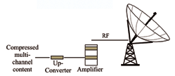
Figure 1. Uplink Chain
Crystal Solutions has created an automated uplink power control and diversity site switching solution which maintains uplink integrity and delivery continuity by compensating for rain fade and automating uplink chain transfers from the primary site to a backup site.
Design Requirements
Sky Latin America is an example of the earliest and most frequently used implementation of site diversity switching controlled by a Crystal intelligent control system. Sky Latin America maintains two uplink sites in Miami Lakes and Port St. Lucie, Florida. Both sites were built with 1:6 uplink redundancy. Each site was designed to be fitted with 30 active uplink chains delivering content to 30 transponders on two different satellites. The intelligent control solution design was required to include:
Automated site switching initiated manually and/or automatically:
• by uplink chain or transponder;
• by satellite (i.e. all chains up-linking to a single satellite must switch on a single command); and
• by uplink RF room (a set of 6 or 12 uplink chains)
Automatic Uplink Power Control (“AUPC”) through the intelligent control system that is independently configured and tested for each transponder’s uplink chain (the uplink path attenuation is different for each chain at each site, which meant both the switching and AUPC logic must be configured and validated accordingly.)
Effective isotropic radiated power (“EIRP”) measurement and monitoring for each uplink chain
A user interface (“UI”) that must be easy to understand and act on under tense operating conditions
Ongoing operational resiliency while managing site switches over a dozen times daily.
A site switching algorithm that induced minimal service interruption—freeze-frame for two seconds or less.
Staggered transponder switching (i.e. must not switch more than one transponder at a time) in order to minimize the impact of the satellite’s automated power control.
Sending In The Solution
Crystal’s intelligent control solution outlined here exceeded Sky Latin America’s requirements without altering any of the core modules or device drivers.
Performance highlights include:
• Reliable site switching that minimized RF anomalies at the affected satellite; no dual illuminations and RF losses of 5 to 10 msec.
• No video disruption by the viewer and minimal audio disruption—an occasional audio pop was all that was experienced.
• Consistent power levels on adjacent transponders were achieved by reducing RF disturbance and by managing switch timing to reduce the satellite on-board power perturbation.
• Recovery from uplink chain failures were achieved within one second.
• M&C allow unrestricted ability to switch uplinks between sites repeatedly.
The Analysis
The entire site redundancy and uplink power control solution was managed by Crystal’s off-the-shelf intelligent control system.
Uplink Attenuation Measurement
To determine atmospheric attenuation, or rain fade, the following equipment was used:
• Radiometer, and
• Beacon receiver
If the budget allows, Crystal’s preferred means of monitoring uplink attenuation is a radiometer due to the advantages this solution provides:
• Better accuracy at uplink frequencies; the loss at a beacon signal frequency has to be converted to a different loss value at the uplink frequencies
• Signal deterioration is calculated in dB of attenuation, which is how a radiometer reports attenuation. The feedback to the operator is simpler and more intuitive to comprehend than the output of a beacon receiver, usually reported in voltage and then converted to dB
• For the same reason detailed earlier, the beacon receiver always demands attenuation be calculated; and this calculation can be unique to the beacon receiver in use (introducing potential for error in the event hardware is replaced, sent out for repair, etc…)
• False switching resulting from sun outages may be avoided since these units consider geographical location, look angle, and time
• Radiometer output is independent of antenna pointing angles thus eliminating the prospect of even modest satellite or antenna positioning changes which may affect a beacon receiver, especially when the antenna is tracking the satellite.
In this application, four radiometers were used between the two sites; a dedicated unit for each satellite at each site.
Beacon receivers were used as backups for the radiometers and testing was performed to validate performance in each system for both the radiometer and beacon receiver.
Uplink Attenuation Monitoring
Attenuation is monitored at each transmission site and for each satellite. If attenuation was detected at both sites then Crystal dynamically selected the best site for uplink based on each site’s attenuation readings.
Automated Site Switching Logic
When attenuation at the primary site reaches user-defined levels the intelligent control system:
• Issues an audible and visual warning that a switch may be necessary
• Increases power to the HPA’s at the offline facility
• Activates AUPC for the HPA’s at the offline facility
• Continues to monitor the attenuation level at both sites
When attenuation breaches a second user-defined threshold, a transmission transfer takes place for each uplink chain that has an available peer uplink at the diverse site. An uplink chain is considered not available if it is in maintenance or has an active alarm condition. The switch-back algorithm is similar: manually returned or automatically reset.
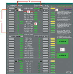
Figure 2. Site Diversity Switching User Interface.
Crystal’s solution for uplink chain switching is considerably different from conventional switching (bringing the backup unit online by tuning the backup amplifier to the proper channel, increasing power and opening a waveguide switch). The result is that service interruption was significantly reduced from seconds to between five and 10 milliseconds. The uplink chain switching sequence involves muting and unmuting up converters instead of relying on the time it takes a waveguide switch to move from one position to another.
This solution performed so well that the 1:6 redundancy in place for an uplink chain failure was changed such that, instead of transferring the service to the backup chain within the facility, it was instead transferred to the alternate site. This new fail-over scheme was much faster and, had this been known during site design, the 1:6 redundancy controllers and the backup chain for each set of uplinks could have been removed from the system entirely. The capital savings for this solution would have been over $500,000.
Handling Satellite Power Management
Switching uplink chains for all transponders on a single satellite simultaneously posed an unnecessary risk of damage or perturbation on the satellite’s on-board automatic power control systems, as well as adjacent transponders. This risk was abated by switching transponders on a single satellite sequentially and with an inter-switch time of approximately two seconds.
User Interface
Given the frequency of site-to-site uplink transfers, a key consideration was to deliver an at-a-glance UI that would allow the operator to quickly identify uplink condition across all 30 uplinks. Furthermore, operators must be able to disable auto-transfer (e.g., when an uplink chain was out of service, under maintenance), and switch all uplinks common:
• To a single transponder
• To a single satellite, or
• To a single uplink room
User Interface Solution
Crystal’s UI was customized to create the most intuitive at-a-glance perspective as possible. The solution was designed as described in the accompanied figure.
Key user interface features:
1. Services are arranged by satellite and are easy to understand.
2. With one button selection, services can be transferred for an entire room or satellite from one site to the other.
3. Services are vertically arranged by location.
4. Large oval indicates service is up from that site while the smaller circles indicate that the backup site is in a condition ready to accept the duty. Circles would turn yellow or red depending on the level of preparedness and/or active alarms.
5. This column of buttons allowed uplink systems to be temporarily removed from the automatic switching solution (e.g. maintenance on individual uplink chain, maintenance on an antenna used for a single satellite) by chain, or the entire satellite.
6.These fields provide real-time radiometer readings in dB of attenuation.
7. These indicators communicated the state of the automation condition. One button was dedicated for each site. These worked as follows:
Green text field (as shown) indicated no atmospheric attenuation and no action was active or pending
Yellow text field indicated attenuation was manifest and HPA’s were in a “ready-to-accept” mode; meaning that they were powered up and ready for content shift and un-muting of the up converter.
Red text field indicated attenuation had breached an acceptable threshold
AUPC + EIRP
The intelligent control system provided an exclusive software solution for both EIRP and AUPC on all 60 uplink chains. Furthermore, as attenuation conditions cleared, the offline uplink chain was placed into a minimal power-consuming operational state: this state maintained the offline chain in a ready condition should the online chain fail.
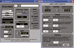
The EIRP and AUPC solutions are managed and configured through each HPA’s remote interface as shown in these screen shots. The interface on the left is a typical Crystal HPA interface. Note the EIRP section on the left side of the screen. AUPC control, calibration, and attenuation are shown in the center bottom. User selection of the Calibrate button launches the second Uplink Power Control screen shown here.
AUPC setup and calibration is highly flexible. Its out-of-the-box configuration satisfied Sky Latin America’s needs and met or exceeded user performance requirements.
Solution Results + Performance
Crystal was able to create a solution without altering any of the core modules or device drivers. All design requirements were met and some requirements were exceeded including:
• Reliable site switching that minimized RF anomalies at the affected satellite; with no dual illuminations and RF losses limited to five to 10 msec.
• Consistent power levels on adjacent transponders were achieved by reducing RF disturbance and by managing switch timing to reduce the satellite on-board power perturbation.
• Recovery from uplink chain failures were achieved within one second.
• The UI allowed unrestricted ability to switch uplinks between sites repeatedly
• Programming interruption was much faster than thought possible and impact was limited to an occasional audio “pop”
In addition, during system testing many discoveries led to a more resilient and high-performance application. These included:
By the up converters mute capability, controlling when RF was actually transmitted to the satellite was more reliable and deterministic than relying on a wave guide switch. This eliminated video interruption and limited programming impact to an occasional audio “pop”.
The Crystal solution was able to execute switching faster than the HPA hardware redundancy controllers. Backup HPAs required a channel changer so that the HPA could be tuned to the correct frequency for the uplink being performed. When the system was set to fail to the 1:6 backup chain the tuning process on the channel changer could take up to 30 seconds. Since there was an HPA at the diverse site pre-tuned to the correct channel, it was significantly faster to transfer service for a failed HPA to the diverse site than to wait for the local backup HPA to change channels. Therefore, in future system designs, uplink chain count can be reduced by 15 percent and hardware redundancy controllers eliminated.
Crystal’s solution positively impacted preventive and reactive maintenance on the uplink equipment: confidence in the system meant that a conditioning of diminishing concern for removal of chains from service.
A result of the successful switching capability of the solution was that the system enabled site switches to occur at any time of the day, which became the standard operating procedure of Sky Latin America. The system was configured with appropriate rain fade thresholds authorizing a dozen or more site switches per day during heavy-rain seasons
Provided… Resilience + Flexibility
Crystal Solutions provided a resilient and exceptionally flexible solution for Sky Latin America using software logic for all aspects of the Automatic Uplink Power Control and Site Diversity needs. Furthermore, this solution was far more flexible than any hardware-based solution available today. With the discovery of the intelligent control solution for uplink chain fail-over, hardware redundancy controllers can be removed and the fail-to chain eliminated from the system design with little increase in risk. As a consequence, and particularly for all but the most elementary automation examples, software solutions such as the Crystal solution can provide more flexible capability at a lower cost and higher performance than alternatives.
Given real-world knowledge and experience from the Sky Latin America Site Diversity system the design of diversity sites can be simplified. Furthermore, significant cost savings can be realized over the traditional model of simply replicating a single site that has normal redundant capability.

Finally, with proper error correction mechanisms, the viewer experience during site switching for video networks can be greatly enhanced by avoiding network-wide outages due to atmospheric attenuation and equipment failure. Learn more at http://www.crystalcc.com.
About the author
Roger Franklin is the President and Chief Executive Officer of Crystal Solutions (formerly Crystal Computer Corporation) located in Duluth, Georgia. He is the principle design architect of Crystal’s intelligent control platform and has worked in the satellite communications industry and with the company since it’s inception in 1986. He holds a B.S. in Mathematics from the Georgia Institute of Technology.