

The changeover of many test ranges from S-band to C-band telemetry implies the need to modify or replace current systems. Several antenna-related issues need to be considered in order to facilitate a smooth transition to C-band. Among these are changes in vehicle-induced pattern degradation, the effect of increased propagation loss on link budgets and the potential need for multi-band antennas that also support legacy systems during the transition.
This article discusses these issues for both existing telemetry systems modified for C-band and for new systems. We will also address conformal and non-conformal antennas in this discussion.
It is fairly well known within the aerospace community that telemetry is moving from the traditional L-band and S-band frequency ranges up to C-band. It is widely understood that the reason for this push to C-band is two-fold. First, traditional L- and S- frequency bands have been greatly reduced through re-allocation, for a variety of reasons by different markets, and second, the bandwidth required for most applications has seen exponential growth. This has not only been seen in military applications but in civilian aerospace platforms as well.
This article focuses primarily on airborne antenna considerations resulting from moving to the higher C-band region, specifically two types of airborne antennas—conformal and non-conformal.
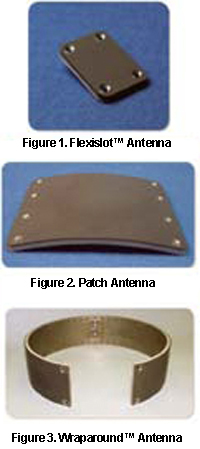
Conformal antennas come in a variety of different shapes, sizes and configurations from discrete radiators such as a Flexislot™ (Figure 1) or a patch antenna (Figure 2) to arrays such as a Wraparound™ (Figure 3).
The Flexislot- or patch-style antennas provide hemispherical coverage while the Wraparound provides omnispherical.
In telemetry applications, it is usually desirable to cover as much of the radiation sphere as possible to ensure data is received during an abnormal event. This is why the Wraparound configuration is often the optimal solution. There are times, however, where it is not feasible to use a Wraparound.
For example, it might not be feasible when there are obstructions on the vehicle that will prevent the utilization of
the full circumference, or when the vehicle geometry is non-circular or physically so large that a Wraparound is simply not possible. As discussed below, the use of discrete elements on large geometries is but one consideration that must be taken into account in this transition to C-band telemetry.
Antenna Construction
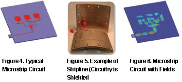
For Wraparounds, there are two construction techniques, namely microstrip (Figure 4) and stripline (Figure 5). Microstrip has typically been the more popular technique and generally works well for L-band and S-band applications. The circuitry used to feed the multiple elements of a microstrip Wraparound is unshielded. The feed is reasonable in size at S-band or L-band. When the frequency is increased 2.5 times, however, this is no longer the case. Unlike the resonant patch, which decreases in size with an increase of frequency, the feed network is nearly invariant with frequency.
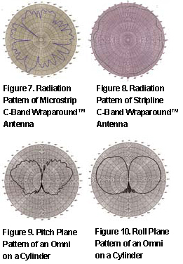
At C-band, the feed network is physically large as compared to individual patches. It is common for high field areas to exist on the feed network itself (Figure 6). Given that the feed network on a microstrip design is unshielded, spurious radiation will occur. The radiation pattern is no longer strictly a result of the energy coming from the individual patches, but is also a function of this parasitic or spurious radiation from the feed network.
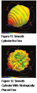
This can result in a very messy radiation pattern (Figure 7). While there are certain design techniques that can be used to reduce the amount of this spurious radiation, it is still unshielded. Stripline construction is fully shielded. It radiates through a series of slots cut out in the ground plane, and can be superior in terms of radiation characteristics (Figure 8, previous page). Control of the pattern shape is one of the most important parts of antenna design.
Vehicle Influence On Radiation Pattern Characteristics
Antennas that provide omni-coverage induce surface currents on the ground plane (vehicle). When these surface currents hit a discontinuity, such as a wing, fin or ground-plane edge, they can radiate. The resulting antenna pattern is then not only due to the contribution from the antenna elements directly, but also the contribution of these additional sources. This can be demonstrated by mounting a hemispherical radiator on a cylinder of 1 meter in diameter. The elevation pattern (with defined ends) contains a ripple (Figure 9) while the roll plane (without defined ends) is smooth (Figure 10). While the changes shown here are not necessarily detrimental, it demonstrates that ground-plane or vehicle effects need to be considered.
To further highlight the impact vehicle geometry can have, the radiation patterns of a Wraparound were calculated when mounted, first on a smooth cylinder, then with strategically shaped and placed fins near the antenna. The patterns for both cases are given in Figures 11 and 12, respectively.
While this is certainly a dramatic case, it is not out of the realm of possibility. It is the authors’ experience that these types of parasitic structures can have a dramatic effect on pattern characteristics and the pattern needs to be considered up front through simulations of the antenna on the vehicle geometry. This will help optimize the antenna design and/or location of the antenna on the vehicle before it is too late.
The effect the vehicle’s geometry has must be considered, regardless of what frequency you are using. It becomes even more important as frequency increases, since fins, wings or other parasitic structures are electrically larger at C-band than at L- or S-band.
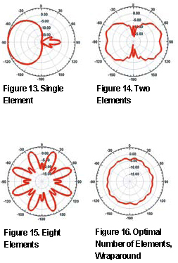
Optimal Number Of Elements To Use
When a full array such as a Wraparound cannot be used, it is widely thought that more is better—this is certainly not the case, as is shown in the following examples.
We start with a single element (Figure 13) and two hemispherical radiators on a cylinder, 180 degrees apart (Figure 14). With the exception of the area directly above and below the pattern, coverage is reasonably good. Adding additional elements results in a precipitous drop in pattern coverage, which can clearly be seen in the eight element example (Figure 15), as this results in rather wide, deep nulls. Eventually there are enough elements added to achieve the optimal number of elements and an omni-spherical pattern is obtained. This is the Wraparound configuration (Figure 16).
As discussed above, it is not always possible to utilize a full circumference Wraparound and so, the next best thing is almost always the two element case. Certainly two S-band elements will have far fewer nulls as compared to two C-band elements on the same diameter cylinder. There are limitations on the number of elements that can be utilized for a given configuration.
Positive Effects Of Moving To C-Band
Due to the small wavelength, C-Band antennas can be made considerably smaller and lighter than their L- and S-band counterparts. In addition, not only does the bandwidth grow proportionally with frequency, but percent bandwidth is actually greater. This means that if you have 100MHz at S-band you will have more than 250MHz at C-band, most likely in the order of 300 to even 400MHz with the same type of design, just scaled up in frequency.
Link Budget Considerations
Not directly related to the airborne antennas, but certainly important enough from a system standpoint, are the effects on link budget when changing from S-band to C-band. The following briefly discuss effects on typical link budget parameters.
Free Space Propagation Loss: There will be a link degradation of approximately 7 dB. Since the free space propagation loss is given by: 10log(4πd2/λ2) [1]
The difference in propagation loss at two different frequencies is equal to: 20log(f2/f1 [2]
Precipitation: The loss due to precipitation will certainly vary with rain intensity; however, you can reasonably expect to realize an additional 2 dB degradation at C-band over S-band in moderate rain.
Cable Loss: Typically with airborne applications, especially with small missiles, it is desired to use the smallest and most lightweight cables possible. If we take a look at a relatively large cable, RG-142, for example, the additional loss associated with 5 GHz versus 2 GHz can be in the order of .5 to 2 dB, depending on the cable length.
Transmitter Efficiency: The transmitter power amplifier tends to be less efficient at C-band so we can add anywhere from 0 to 3 dB degradation attributed to the transmitter as compared to use at S-band.
Total Degradation Delta: Considering all of the above items can result in a total degradation in the link, between 7.5 to 14 dB, when comparing C-band to S-band. While this is not meant to focus heavily on any specific link, it should not be overlooked. While it is not the intention to discuss ground antennas, it should also be noted that an increase in ground antenna gain can make up some of these differences in link degradation. This does, however, result in a much narrower beam, which can cause some tracking issues if not handled correctly.
Transition Antennas
While the transition to C-band is taking place, certain areas are still utilizing L-band and S-band. It is, therefore, highly desirable to have an antenna that will handle all three—L-, S- and C-band—as using a one antenna solution simplifies system change over.
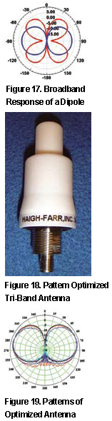
Monopole and dipole antennas naturally provide multi-band performance with regard to voltage standing wave ratio (VSWR), however, only the lowest frequency band provides the desired radiation pattern, as illustrated in Figure 17. A common mistake observed by the author is utilizing the VSWR solely to evaluate antenna performance. To get the full picture, radiation patterns must also be considered.
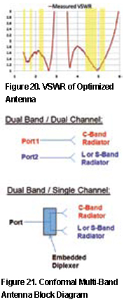
There are antennas specifically designed to maintain radiation pattern characteristics over frequency. An example is shown in Figure 18. The radiation patterns of this antenna are essentially invariant as a function of frequency (Figure 19). The minor differences observed are actually caused by the ground plane changing in electrical size as we go from 1.4 to 5.25MHz. The VSWR of this antenna is well under 2:1 over all of the telemetry bands, as indicated by the yellow highlighted areas (Figure 20).
Conformal Multi-Band Antennas
There are several ways that both S-band and C-band or all three (-L, S- and C-band) can be achieved in a conformal design. Certainly, the simplest is to have a dual-band antenna with two distinct arrays within the same physical package and two distinct connectors as shown in the block diagram (Figure 21). This would result in possibly having to change to the correct RF connector (band) before use. An alternate approach embeds a diplexer inside a conformal antenna, L- or S-band radiators for legacy systems and C-band radiators, which are all fed through the embedded diplexer. This results in a single port design. It is also possible to do this with a tri-band configuration L-, S- and C-band.
Given that the C-band, L-band and S-band radiators are optimized for their respective bands, pattern characteristics would be the same and there would be no degradation. This multi-band conformal antenna would require additional space over the legacy L- or S-band antennas. In some cases it may not be feasible to change the vehicle geometry to accept this larger antenna, but a C-band antenna can always be packaged to replace the lower-frequency legacy units.
Conclusion
There are several antenna considerations when changing from the legacy bands to C-band for telem wrong construction type, number etry. Choosing the of elements and/or placement can have a major impact on overall performance.
While all of the effects cannot be fully mitigated, in most cases performance can be optimized, which will result in a successful link.
More information is available at the Haigh-Farr infosite at (http://www.haigh-farr.com/)