
Interference can mean many different things in SATCOM. For VSAT ground stations, three major contributors can be applied to both GSO and NGSO satellites in similar ways:
• Set-up and calibration
• Power control
• Inadequate antenna design and performance
Set-Up and Callibration
VSAT terminals can cause interference from poor cross-polarization isolation. When setting up and commissioning a manual VSAT terminal, the ground operator must “Peak and Pol” or accurately point to the correct satellite and perform a polarization skew. Peaking refers to optimal pointing and the terminal transmitting just the right power. In the case of linear polarization, we want the cross-pol to align very precisely with the satellite and this often requires coordination with the satellite operator who is especially concerned with their network efficiency and detecting and mitigating interference.
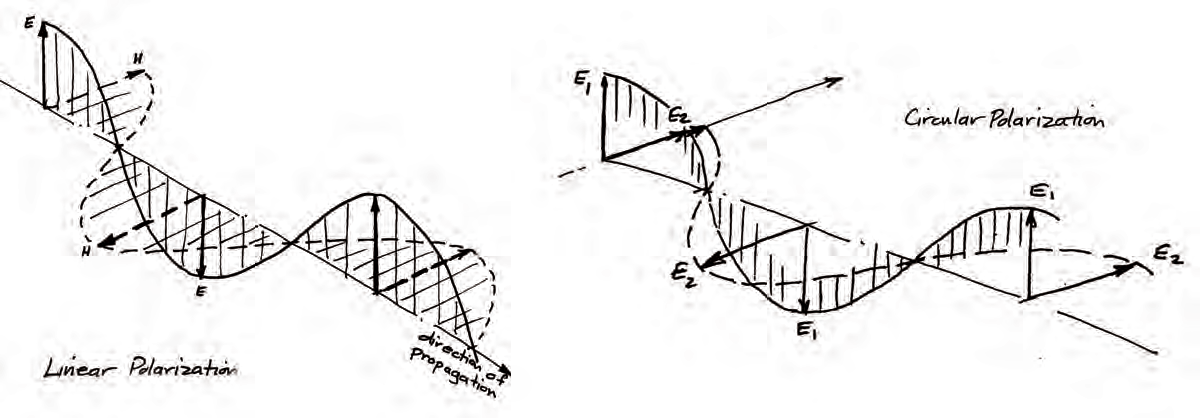
Circular-polarization is either right-hand or left-hand but does not require a skew to the satellite. Fully-automated satellite acquisition and peak-and-pol is built-in to terminals manufactured by AvL Technologies and others. For tracking antennas this process is fully automated as well.
With GSO satellites, a common source of adjacent satellite interference (ASI) occurs when the user of a VSAT ground station applies too much RF amplifier power and thereby exceeds the spectral density specification resulting in ASI. Automated power controls built into modems are effective at mitigating this type of interference but it is still an issue due to the increasing power and decreasing size, weight and cost of amplifiers.
Modern solid-state amplifiers are manufactured using gallium nitride which allows for higher voltages and faster current flows than silicon. For a few bucks more, users will often double their power from a 25W BUC to a 50+W BUC. The ground station operator wants more throughput and it is readily available today – but in the hands of an untrained user, increased power has the potential to exceed the specifications of the VSAT and cause ASI.
Power Density is the single most important operating parameter for transmitting earth stations and probably the least understood by operators of satellite communication terminals.
Most terminal operators can tell you how much power is being used to transmit as well as the data rates achieved up and down. This is good information to know, but it is not good enough to ensure the terminal is operating at its best and within regulatory limits. The official document issued by the satellite operator or regulatory agency like the FCC that authorizes a terminal to transmit specifies its maximum allowed power density.
Operating a terminal without knowing the current value of this critical parameter can lead to two very negative results:
(1) self-interference due to transponder overload, and,
(2) excessive interference with other users on the same and neighboring satellites.
Either of these outcomes, especially interfering with others, could lead to the temporary or permanent revocation of a terminal’s license to transmit.
Every transmitting Earth station must obtain a license in order to operate and power density is what can get them in trouble. Unfortunately, the license document typically offers no guidance regarding what the specified maximum power density value means in terms that operators are familiar with, such as high-power amplifier / block up-converter (HPA / BUC) power level, data rate and modulation type. Few terminals directly monitor or control power density, but almost all allow the operator to change it. For that reason, it is relatively easy for the operator to unintentionally turn his fully compliant and approved terminal into a very effective source of interference on his, and other, satellite communication systems.
What is Power Density? Simply put, power density describes how the transmit power in a communications signal is distributed over frequency. It is expressed in terms of power divided by a relatively small unit of bandwidth (e.g. dBW/4kHz) and is usually referenced to the input of the satellite terminal’s antenna. The unit dBW, or dB-Watts, is the universally accepted way of expressing power on a logarithmic scale. Bandwidth is a factor since all satellite signals spread their power across a range of frequencies.
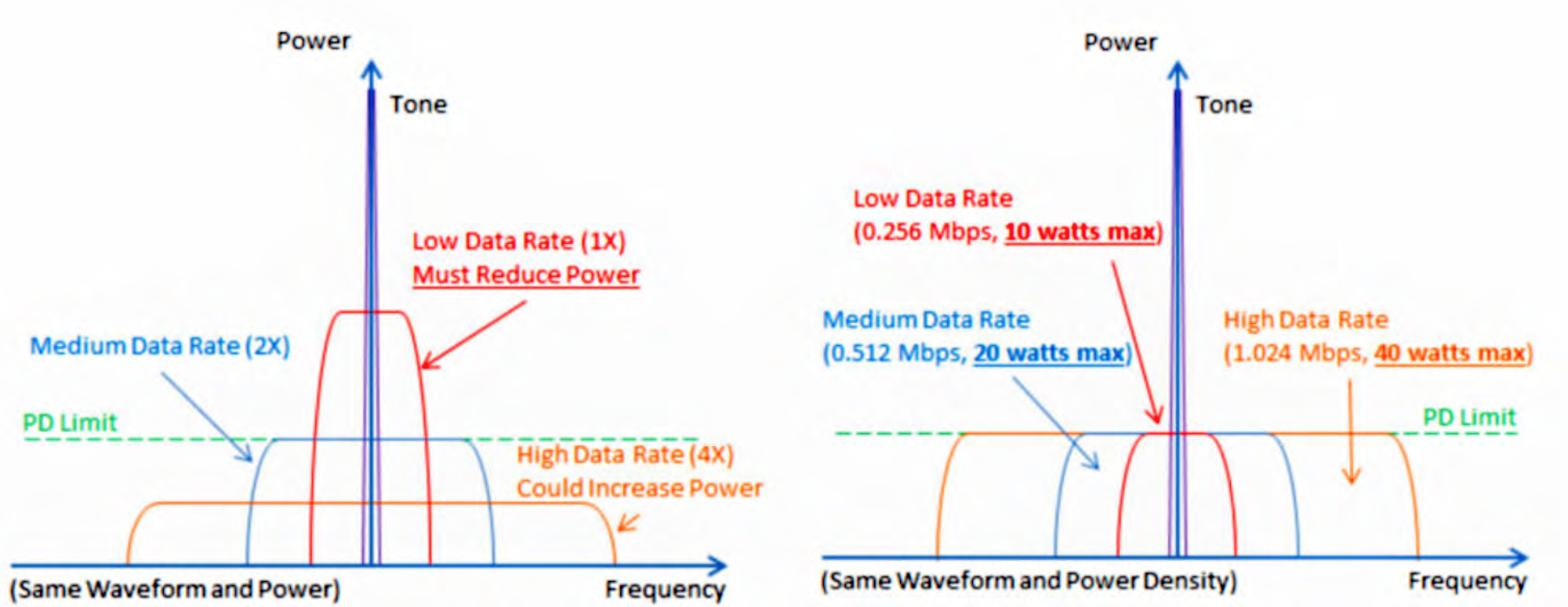
The speed at which digital information flows is the data rate of the signal. In general, as the data rate of a signal increases, so does the range of frequencies occupied by that signal. Assuming total power in the signal is constant; increasing the data rate will spread power over a wider range of frequencies and decrease power density.
The inverse is also true. The illustration below shows the power spectrums of several data signals. All use the same waveform (modulation and coding). As shown in the illustration, a simple change to data rate can make a substantial change in power density and lead to operation well above or below the power density target or limit.
Power density figures prominently in the design of a satellite network that must make optimal use of its assigned transponder bandwidth. Every terminal in the network is allocated a certain power level and carrier bandwidth such that all users combined optimally load the satellite transponder. A terminal operating at slightly below its allocated power density level suffers little ill effect and will cause no issue to others. However, operating above the power limit can quickly lead to an overload condition that degrades communication channel performance for that terminal and every other terminal sharing that same transponder, including users that may not be on the offending terminal’s network.
Transponder overload was a common and very serious problem when most remote terminals operated “open-loop.” Today, the vast majority of terminals “close the loop” with the network operations center and adjust their transmit power density based on the amount of power received on the other end of the return link. This power management approach is referred to as uplink power control (UPC). With UPC the network operator can ensure the system is getting maximum usage of the satellite resources assigned to the network without overloading the transponder. However, all risks associated with excessive power density are not removed by UPC.
Antenna Design and Performance
In the early days of Ku-band satellite licensing and the build-out of services, most of our industry’s attention was focused on the terminal antenna’s sidelobe performance and maximum allowed effective isotropic radiated power, or EIRP. That focus gave rise to the now famous, at least among antenna designers, 29 - 25 log - dBi curve.
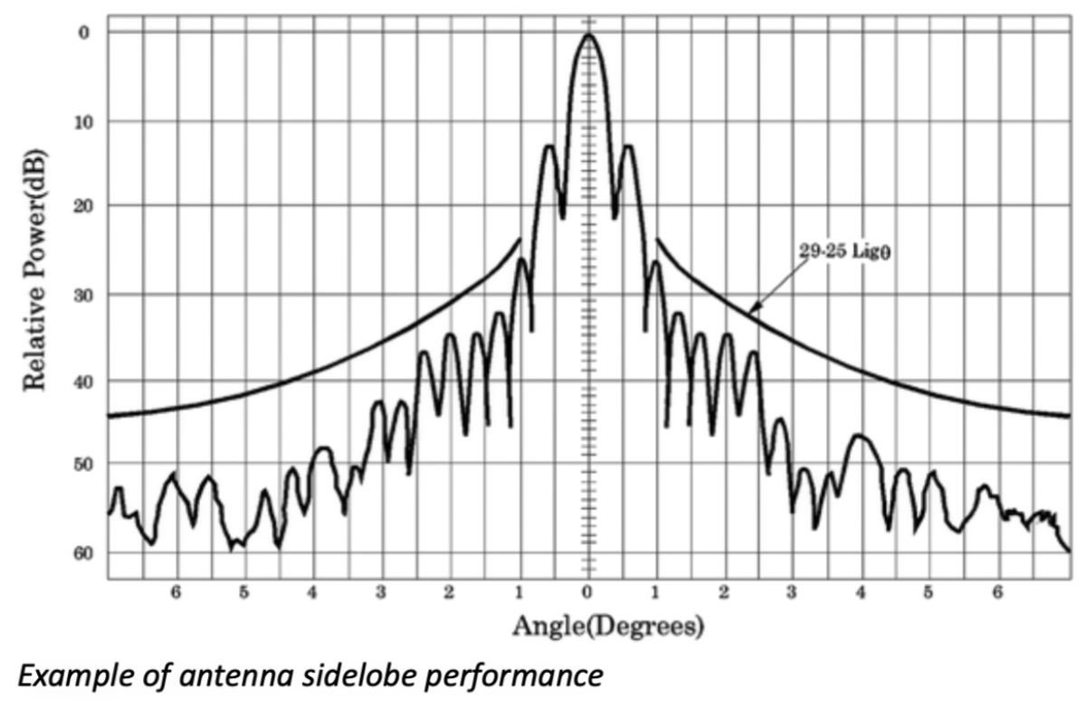
When plotted along with the pattern of a parabolic reflector antenna optimized for use in a satellite system, this curve follows the peaks of the antenna’s sidelobes very well out to a relatively large angle (> 30 degrees). A terminal’s EIRP is a measure of its raw power and is calculated by adding the maximum power produced by the HPA/BUC (in dBW, dB-Watts) to the peak gain of the antenna (in dBi, dB-isotropic).
As technology has led to development of advanced waveforms, signal modulation and coding, the character of satellite links changed. Knowing the maximum EIRP of an interfering signal is no longer enough information to make reasonable design decisions or quality of service commitments. A terminal operator who does not keep the power density within strict limits could become a problem interferer and lose the license to transmit.
Will the second pioneering race to space be plagued with interference due to the issues described so far? Already quite a lot of interference exists from both avoidable and unavoidable sources but the probability increases with every launch.
Interference mitigation requires intentional planning and thoughtful coordination and compliance by all parties involved. It requires extreme situational awareness from space management systems, ongoing monitoring and control and strategic location of ground stations.
While not every LEO constellation will survive the path to full scale operation, those that do will hire the best talent and the best services to solve these problems with solutions like artificial intelligence, machine learning and by methods we probably haven’t even thought of yet.

Bryan Kerns joined AvL Technologies in 2010 and serves as the company’s Director of Strategic Business Development and Information Technology. Prior to joining AvL, Bryan was an AvL customer at companies including GTSI, Verizon Business, LBiSat and Harris CapRock Communications. He began his career as a USAF Communications Officer. With 24 years of experience in satellite communications, Bryan has authored numerous articles and spoken about the use of satellites to communications and disaster planners from agencies including Army, Air Force Space and Missile Defense Commands, Defense Information Systems Agency, White House Communications Agency, and the Department of Homeland Security. Bryan is a founding Key group member of the Asheville, North Carolina, chapter of Vistage International. He has a Bachelor’s degree from North Carolina State University and a certificate in Disruptive Strategy from Harvard Business School.