Space-COTS are Commercial-Off-The-Shelf components that have been qualified for space applications and that follow international standards. Thanks to a new industrial test concept, Space-COTS match small satellite mission requirements efficiently and offer the best Price/Quality ratio for space hardware manufacturing.
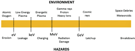
Figure 1: Space Environment and related Hazards. Source: Spectrum Aerospace
The space environment is surrounded by different physical phenomena and electronic space systems will be affected in one way or another. For a space mission, the environment must be well understood in order to avoid damages and malfunctions in onboard electronics.
The exact behavior of such physical phenomena in a specific space mission depends on the satellite’s orbit. The behavior can be accurately simulated with software tools and these results assist satellite developers in appropriately designing their systems.
In the space environment, the following physical phenomena can be found:
Atomic Oxygen
UV light break the O2 molecules in single Oxygen atoms. The atomic Oxygen is very reactive and erodes the surface of the satellite structure. This rust affects the thermal behavior of the structure and of the satellite. This is an important issue as spacecraft thermal control will be impacted.
Plasma
The ionized gases generate electrostatic charges and load onto the surface of the satellite. The discharge of such loads can affect the operation of the satellite and of the instruments.
Radiation environment
A variety of effects belong to this phenomena. Gamma rays degrade the electronic components. Protons and heavy ions can literally destroy the electronics of the satellite or in the best case corrupt digital data.
Micrometeoroids and space debris
The most dangerous elements in the space environment are small artificial or natural bodies. The impact of a micrometeoroid or other space debris can damage or destroy the satellite. Such situations have already occurred and the consequence was spacecraft loss.
At the start of the space era, there were no space electronics available. Military electronic parts were up-screened for their use in space. In that process, complementary tests were achieved and those with the best results were selected for implementation in the mission.
In 1973, the Skylab hardware was manufactured using military components. After the qualification test, the hardware had to be improved several times due to malfunctions that were encountered during the qualification process. These improvements required the further investment of more than three million dollars to obtain system redundancy; new electronic components and further qualification campaigns were then additionally required.
The electronic systems of the first space shuttle mission (1981) were also based on military components. In order to increase the reliability of the system, most of them were built with sixfold redundancy. The valid data was verified using an elective process. The inclusion of redundant systems also meant an increase in weight and power consumption which, in turn, presented additional hardware and software challenges.
Due to the fact that these earlier military electronics were not good enough for space applications, and that the up-screening did not always improve the parts being considered, in the 60’s the systematic development of space electronics was initiated, as they had to meet or exceed high quality production process standards. In the US, military components were selected and then qualified after running additional tests. This strategy allowed for the reduction in production costs. As the demand for space components was, and is, minimal, the price of these units remains high.
Today, the qualification of a single component that follows the ESA or NASA standards implies an investment that starts from an expenditure of one million dollars and a certification time of approximately two years [1].
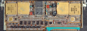
Figure 2: Space shuttle (1981) IBM CPU - AP-101. Source: NASA
The experience gained over the last 60 years in many space missions and with different technologies has allowed organizations such as the ESA and NASA to develop sound qualification guidelines and standards. These are manuals to be followed and used for the qualification of electronic parts for space missions.
The standards defined by the ESA can be found in the European Space Components Information Exchange System (ESCIES) website (escies.org/webdocument/showArticle?id=167).
A database of qualified electronic components, including their test reports, is also available at the ESCIES Website. (https://escies.org/labreport/radiationList).
The validation and qualification process is comprised of the hardware and device preparation (Device Under Test or DUT) to be tested, the execution of the test and then the evaluation of the results. The results are then published in a test report.
Depending on the mission, in some cases the screening of a few parts is not enough to guarantee the qualification of the entire system (e.g., radiation tests)—in other cases, the complete batch (outgassing) has to be tested.
During the tests, the relevant parameters of the devices will be characterized under space conditions. One important point for a successful qualification is to guarantee that the tested components were each produced using a similar manufacturing process—all of the qualified parts should be identical (geometry, size, materials, etc.) and, consequently, they then belong to the same batch. After the qualification, a test report and a datasheet will be generated containing the parameter values and limits relevant for the use of the electronic parts in space.
A full qualification of a component is quite laborious, requires a few years and demands a high financial investment. A full qualification is called a “Screening Test.” The following tests must be performed:
• Electrical test
• Seal test
• Visual inspection
• Mechanical shocks
• Vibration test
• Constant acceleration
• Thermal test
• Radiation test
• High Temperature Stabilization Bake
• Temperature cycling
• Thermal Shock
• Solderability
Following the ESA Standards that are described in the document “ECSS-Q-ST-60-13C_Space product assurance” three different classes are defined [2].
The difference between the classes depends of the depth of the qualification process. In summary, Class 1 represents a full qualification. Class 3 represents a light qualification, mainly radiation testing.
To show how a qualification test is conducted, here is a short description of the Total Ionizing Dose (TID) test:
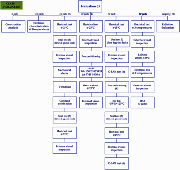
Figure 3: ECSS-Q-ST-60-13C Evaluation tests flow Class 1. Source: ESA.
—Preparation of the DUT test boards. Here, two configurations (Bias Condition) are important. One is the “Off-Mode,” where all the pins are connected to ground.
—The second one is the “On-Mode,” where the device is configured in a specific operating state but will be retained without function, such as in “Stand-by” mode. This mode means no signal will be processed during the test.
This two test configuration will be used for the irradiation of the DUTs. Cobalt-60 will be used as radiation source. During the irradiation, the DUTs will be characterized in time intervals with a tester (Automatic Test Equipment – ATE). The characterization results will show the degradation of the devices during the test. The degradation depends on the accumulated radiation dose. For example, the power consumption will increase the higher the radiation dose received. Upon completion of the test, it is possible to observe the variation of some electrical parameters and, in some cases, where a specific radiation dose results in the destruction of the device.
Over-Qualification? Are COTS Robust Enough?
ITAR components comply with severe requirements and offer high reliability for their usage in extreme environments. An ITAR component can have a radiation tolerance of 300 krad.
During an LEO mission, a total dose of 1 krad will be accumulated in one year [4]. In this case, the use of ITAR components does not match the mission requirements—ITAR components are over-qualified for LEO missions is a valid statement.
Problematic are the ITAR export restrictions. The export licensing process takes approximately six months to complete and there is no guarantee permission will be obtained in the final run. This is definitely a major problem for small and medium-sized enterprises (SMEs) and retards their business processes. Another disadvantage—the ITAR EEE parts are based on a robust, albeit old technology, and do not satisfy the latest high-tech electrical and functional levels.
Another important point is the price of ITAR components, which are high and financial obstacle for SMEs that wish to enter the space business but are not in possession of major capital resources.
Evolution Of An Era
The new space era began with the birth of smallsats. In February of 2000, Stanford University launched their OPAL smallsat. OPAL was the mothership for six picosatellites and demonstrated the feasibility of new space platforms for research experiments [5].
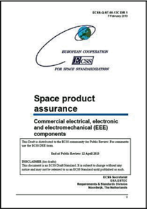
Figure 4: ECSS-Q-ST-6-13C Standard. Source: ESA
These new space platforms have been in use by many universities, research institutes and space companies for a variety of research missions, technology demos and validations as well as commercial services. In order to keep costs low, COTS components are being used. These components support the missions for a limited period of time. Now, however, the use of COTS components in space has experienced a rebirth [6].
Many institutions continue developing and launching smallsats that are built using COTS. Most of these missions never qualify the electronic components being used—there is trust that the pre-launch simulations are accurate and a certain amount of luck is required.
In the best case, the developing teams test the electronics. During this process, the electronic board will be irradiated with gamma rays and run with test software until errors appear. Should nothing untoward occur, the test will be considered as having passed.
This is not a professional way to develop space electronics. The standard procedure from the ESA and NASA for testing each component is the recommended method to implement in the design of electronics for space, especially as it is necessary to understand the behavior of all components under such harsh conditions.
Each component of the system should be tested in order to comply with mission requirements—the components must be selected prior to the implementation of the mission design. The uncertainty of not knowing the life expectancy of the electronics will slow the professional development of smallsats.
NewSpace
NewSpace is a term that relates to the emerging, private space industry.
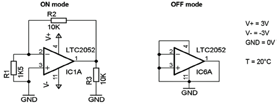
Figure 5: BIAS Condition TID Test for the LTC2052. Source: Spectrum Aerospace.
This community is mainly comprised of space companies that are involved in the development of low-cost space technologies and the establishment of low-cost policies.
Through these efforts, space technology will become a mass market product and will be practically accessible to everyone [7]. An important note is that ITAR solutions currently do not match the NewSpace philosophy and, in consequence, new solutions must be found.
One of the most interesting parameters for devices in space is radiation robustness. This parameter cannot be found in commercial parts datasheets. All electronic components could certainly survive in space—but the questions becomes… for how long?
In the datasheet of a commercial component, the behavior of the electrical parameters under normal conditions (on the ground) will be assessed and the limits described. For instance, in a datasheet it is possible to read the Absolute Maximum Ratings such as the temperature limits, let say, from -10° C to +50° C. This doesn’t mean that under or above these limits the component will not function.
A test in a thermal-chamber will reveal the true limits of the component. This means the same components could be used for a broader temperature range than specified in the datasheet. In general, it is possible to see how robust an electronic component is by measuring its behavior under specific environment conditions.
The NewSpace philosophy and the approach described above are merged into the Space-COTS project and the emerging, private, space industry.
The Story Behind Space-COTS
The term—Space-COTS—and the concept were invented by Jaime Estela from the German/Peruvian company Spectrum Aerospace. The research work was completed with Martin Canales Romero and Avid Román-Gonzalez in support of smallsat projects in Europe and in South America. These projects have paid off in a deeper knowledge and understanding of smallsat technology and the technology’s requirements and constraints.
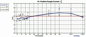
Figure 6: OPAMP power supply degradation. Source: Spectrum Aerospace.
Furthermore, the experience of these three researchers corroborated the use of commercial electronics in the space business. Working for the German Aerospace Agency (DLR) in satellite projects, with close reference to the ESA standards, has resulted in an understanding of the long and expensive pathways required for the traditional qualification of EEE parts.
The DLR’ Standardization and EEE-Parts Division and the ESA Component Space Evaluation, as well as the Radiation Effects Section, all instructed the Spectrum Aerospace team in the concept and philosophy of the test procedures for EEE parts.
These experiences crystallized in the concept of Space-COTS finding the middle point between having no qualified parts whatsoever and fully qualified ITAR parts. Looking at smallsat history, many commercial parts can work in space for several years even though many were not designed for space applications.
Reliable, commercial EEE parts must be identified. In mid-2015, due to the participation in the Horizon-2020 program, a feasibility study was conducted, where author Jaime Estela evaluated the components used in different satellites and identified the most used parts.
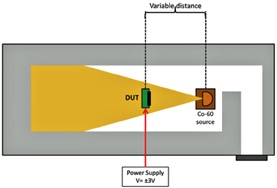
Figure 7: Co-60 facility. Source: Spectrum Aerospace.
The result of this study led to the first edition of the Space-COTS catalog, which will be soon be published in the community portal at space-cots.com. The aim of this catalogue is to list the major qualities of active and passive electronic, electric, and electro-mechanic parts that cover almost all space mission needs.
Space-COTS will be tested and qualified in different levels, depending on the depth of the qualification as follow:
• Class A: Full screening test
• Class B: TID and SEE test
• Class C: TID test
These classes follow the ESA/NASA Standards and also the new standards coming from the International Organization for Standardization (ISO). The more intensive the test, the higher the cost of the qualified devices and equipment. Regardless, this solution is much less expensive than for ITAR products. The Space-COTS catalog is classified in component groups. Each group involves the same type of components. The following groups were defined:
• Diodes
• Bipolar
• Transistors
• FET
• Power
• MOSFETS
• OPAMP
• Comparators
• AC/DC converter
• Voltage regulator
• Voltage references
• ADC/DAC converter
• Logic devices
• Drivers
• Memories
• Controllers
• FPGAs
• Sensors
• Image sensors
• Optoelectronic parts
• And more...
The qualification of COTS inside one project, where one or few exemplars are needed, does not justify the qualification of each component as the test cost will considerably increase the project budget. Taking such into account, Spectrum Aerospace will achieve the qualification of representative numbers of COTS and will bring these into the space market at competitive pricing. Spectrum Aerospace has designed test environments that allow for the qualification of a large number amount of parts and within a short time period.
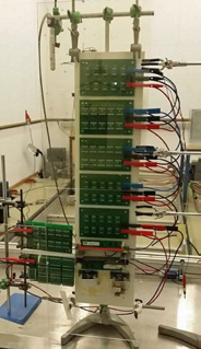
Figure 8: Stand of DUTs ready for the irradiation. Source: Spectrum Aerospace
One important point to mention is that new generation components will be included within a short timeframe in the Space-COTS catalog and this information will be quickly become available. Spectrum Aerospace identifies the best COTS, qualifies the product and then offers the product to the smallsat community at the best price possible.
The Smallsat Market
The market for smallsats is rapidly growing and new technical solutions and services are necessary to satisfy increasing demands. For the manufacturers of smallsat electronics, ITAR components are not the correct solution—Space-COTS could certainly fill this important role.
A similar case holds true for satellite launchers. Smallsat will never fly a space mission as long as there are no dedicated launch services available to push them into their required orbits. The piggyback solution is an emerging solution.
Forecast studies completed by the research company NSR indicate that more than 2.500 smallsats up to 100 kg will be launched within the next 10 years [10]. Another forecast by the Spacework predicts that from 2014 until
2020, three thousand small satellites (in weight up to 50 kg) will be launched [11]. In both forecasts, future satellite constellation were also considered. The use of constellations promises several benefits, such as:
• A smaller number of satellites needed
• Reduction of mission costs
• Reduction in the number of launches and the size of the launcher
• Higher performance due to availability of redundant satellites
More electronic parts will be required and Space-COTS will be able to satisfy this future demand, thanks to efficient qualification processes (quality assurance), competitive prices (cost reduction) and a broad portfolio.
Future Activities
Space-COTS represents the efficient investment of funding and provides each project with EEE parts that satisfy exact mission requirements, with attractive prices, with a corresponding quality level and, especially, without over-qualification.
In order to support the entrance of new solutions into the space field, new standards must be defined. The ISO organization began to treat this situation starting with the edition of new standards. On the ISO website under the term “Design Qualification and Acceptance Tests,” the defined standards related to the space field can be found.
The document related to the components qualification topic is the “Space Systems—Design Qualification and Acceptance Tests of Small-scale Satellite and Units Seeking Low-cost and Fast-Delivery.” Topics such as qualification test, acceptance test, retest, test plan, test report, test requirements, test levels and duration, Total Ionization Dose test, Single Event Effect test, Electrostatic Discharge test, Electromagnetic Compatibility test and others will be handled in this document [8]
New Methods For Qualification Tests
Looking into the future, Spectrum Aerospace is planning and coordinating technical solutions to improve the effectiveness of the qualification process via dedicated methods in order to reduce cost and time yet, all the while increasing quality.
Some of these selected technologies will be used soon and others will still require research activities to bring the technology to industrial standards. Spectrum Aerospace will continue this work and will regularly present the progress of these activities, especially as the evolution of Space-COTS is now underway.
The future of the space industry is in the hands of disruptive technologies which match smallsat mission requirements. Space-COTS is one of the disruptive technologies that will aid in the creation and expansion
of NewSpace.
www.spectrum-aerospace.com/
REFERENCES
[1] The history of space quality EEE parts in the United States, http://www.cti-us.com/pdf/HistoryEEESpacePartsinUSA.pdf, Leon Hamiter, Components Technology Institute Inc., 904 Bob Wallace Ave., #117, Huntsville, Alabama 35801 USA.
[2] ECSS-Q-ST -60-13C_Space product assurance, ESA Requirements and Standards Division ESTEC, P.O. Box 299, 2200 AG Noordwijk, The Netherlands.
[3] Spectrum Aerospace ESCIES Test Reports, https://escies.org/download/webDocumentFile?id=63442, https://escies.org/download/webDocumentFile?id=63441.
[4] Extreme Environment Electronics, John D. Cressler & H. Alan Mantooth, CRC Press—Taylor & Francis Group.
[5] A rocky road to outer space, https://news.stanford.edu/news/2001/january31/opal-131.html, Stanford Report, January 31, 2001.
[6] CubeSat: A new Generation of Picosatellitefor Education and Industry Low-Cost Space Experimentation, Mr. Hank Heidt, Prof. Jordi Puig-Suari, Prof. Augustus S. Moore, Prof. Shinichi Nakasuka, Prof. Robert J. Twiggs, 14TH Annual/USU Conference on Small Satellites.
[7] https://en.wikipedia.org/wiki/NewSpace.
[8] ISO—International Organization for Standardization, Space systems—Design Qualification and Acceptance Tests of Small-scale, Satellite and Units Seeking Low-cost and Fast-Delivery, Online document name: ISO_TC_20___SC_14_N_949.pdf.
[9] Assessment of sensor performance, C. Waldmann, M. Tamburri, R. D. Prien, and P. Fietzek, Ocean Sci., 6, 235 –245, 2010, www.ocean- sci.net/6/235/2010/, Published by Copernicus Publications on behalf of the European Geosciences Union..
[10] NANO AND MICROSATELLITE MARKETS Report, Northern Sky Research, LLC, One Mifflin Place, Suite 400, Cambridge, Massachusetts 02138.
[11] Small Satellite Market Observations 2015—Forecast, Dr. John Bradford, Spaceworks Enterprises Inc., 1040 Crown Pointe Parkway, Suite 950, Atlanta, Georgia 30338 USA.