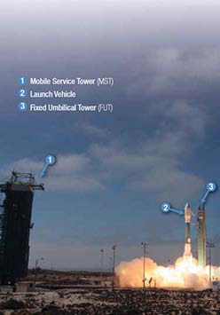
A United Launch Alliance Delta II 7320-10 launch vehicle delivered the Orbiting Carbon Observatory (OCO-2) satellite to a 370-nmi (686km) near-circular orbit on July 2, 2014. Liftoff occurred from Space Launch Complex 2W at Vandenberg Air Force Base, California.
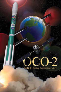
OCO-2 is NASA’s first spacecraft dedicated to studying atmospheric carbon dioxide (CO2), the most significant human-produced greenhouse gas and the principal, human-produced driver of climate change.
OCO-2 will collect space-based global measurements of atmospheric CO2 with the precision, resolution, and coverage needed to provide the first complete picture of the regional-scale geographic distribution and seasonal variations of human and natural sources of carbon dioxide emissions and their sinks—the reservoirs that pull carbon dioxide out of the atmosphere and store it.
The OCO-2 mission provides a key new measurement that can be combined with other ground and aircraft measurements and satellite data to answer important questions about the processes that regulate atmospheric CO2 and its role in the carbon cycle and climate.
The Orbiting Carbon Observatory is managed by NASA’s Jet Propulsion Laboratory (JPL), Pasadena, California, for NASA’s Science Mission Directorate, Washington, D.C.
Orbital Sciences Corporation, Dulles, Virginia, built the spacecraft and provides mission operations under JPL leadership.
NASA’s Launch Services Program at NASA’s Kennedy Space Center in Florida is responsible for launch management.
The Launch Vehicle
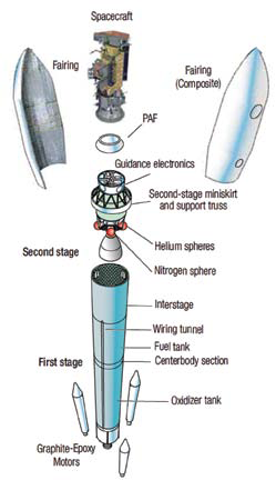
Payload Fairing (PLF)
The PLF is a composite bisector (two-piece shell), 10 feet in diameter fairing. The PLF encapsulates the spacecraft to protect it from the launch environment on ascent. The vehicle’s height, with the 10 feet PLF, is approximately 128 feet.
Delta II Second Stage
The Delta II Second Stage propellant tanks are constructed of corrosion-resistant stainless steel. The Delta II second stage is a hypergolic- (Aerozine 50 and Nitrogen Tetroxide) fueled vehicle. It uses a single AJ10-118K engine producing 9,850 pounds of thrust. The propellant tanks are insulated with Dacron/Mylar blankets.
The second stage’s miniskirt/guidance section provides the load path for the payload to the booster as well as the structural support for the second–stage propellant tanks, the PLF, mountings for vehicle electronics, and the structural and electronic interfaces with the spacecraft. The second-stage, other than the mini-skirt, is nested inside the interstage adapter.
Booster
The Delta II booster is eight feet in diameter and approximately 87 feet in length. The booster’s fuel and oxidizer tanks are structurally rigid and constructed of stiffened isogrid aluminum barrels and spun-formed aluminum domes. The booster structure is completed by the centerbody that joins the fuel and oxidizer tanks and the LO2 skirt, which joins the tank structure to the engine section.
Delta II booster propulsion is provided by the RS-27A engine. The RS-27A burns RP-1 (Rocket Propellant-1 or highly purified kerosene) and liquid oxygen, and delivers 200,000 pounds of thrust at sea level.
The Delta II booster is controlled by the second-stage avionics system, which provides guidance, flight control, and vehicle sequencing functions during the booster and second-stage phases of flight.
Solid Rocket Motors (SRM)
The Delta II 7320-10 launch vehicle uses three SRMs, approximately 40 inches in diameter and 42 feet in length. The SRMs are constructed of a graphite-epoxy composite with the throttle profile designed into the propellant grain. The SRMs are jettisoned by structural thrusters following a 63-second burn.

The Delta II is part of a launch vehicle family that first entered service in 1989 and has recorded well over 140 successful launches to date. The Delta II has also been selected to place a number of other Earth-orbiting satellites into orbit, including SMAP (Soil Moisture Active Passive) mission and ICESat-2.
Delta rockets have been carrying NASA spacecraft aloft since the 1960s. You can share the excitement that was at the live countdown via NASA TV or the web.
The Satellite
The Orbiting Carbon Observatory-2 (OCO-2) satellite is designed to make the first space-based measurements of atmospheric carbon dioxide (CO2).
Looking at the satellite’s history, the initial Orbiting Carbon Observatory (OCO) was a NASA Earth System Science Pathfinder Project
(ESSP) mission designed to make precise, time-dependent global measurements of atmospheric CO2 from an Earth orbiting satellite. Unfortunately, on February 24, 2009, due to a launch vehicle payload fairing anomaly, OCO failed to reach orbit. However, in December of 2009, the Congressional Conference committee directed NASA to allocate no less than $50M for the 2010 fiscal year (FY10) for the initial costs associated with an OCO replacement. Released on February 1st, 2010, the President’s Budget provided adequate funding to support the launch of an OCO re-flight mission (now known as OCO-2).
The OCO-2 mission underwent critical design review (CDR) in August 2010 and key design point-C (KDP-C) in September 2010. On October 2010, it began the implementation phase.
On July 16, 2012, NASA announced that it had awarded launch services contracts for three United Launch Alliance Delta 2 rockets. A little over five years after the OCO launch failure, OCO-2 manifest stated the launch, from Vandenberg Air Force Base would take place No Earlier Than (NET) Tuesday, July 1, 2014, which was successful. Originally flown on a Taurus XL, OCO-2 is now flying on a Boeing Delta II 7320-10C. The Delta II is one of the most successful launch vehicles ever flown with well over 100 successful launches.
The Mission
OCO-2 was built based on the original Orbiting Carbon Observatory mission to minimize cost, schedule and performance impacts. OCO-2 is designed to have a nominal mission time frame of at least two years, but the spacecraft could continue to fly well beyond its prime mission. OCO-2’s primary science objective is still to substantially increase the understanding of how carbon dioxide sources and sinks are geographically distributed on regional scales and how their efficiency changes over time.
OCO-2 will not be measuring CO2 directly; but actually, the intensity of the sunlight reflected from the presence of CO2 in a column of air. This measurement is unique like a fingerprint, and can be used for identification. The OCO-2 instrument will use a diffraction grating (like the back of a compact disk) to separate the incoming sunlight into a spectrum of multiple component colors.
The instrument measures the intensity of three relatively small wavelength bands (Weak CO2, Strong CO2 and Oxygen O2) from the spectrum, each specific to one of the three spectrometers. The absorption levels will indicate the presence of the different gases. By simultaneously measuring the gases over the same location and over time, OCO-2 will be able to track the changes over the surface over time.
The OCO-2 spectrometers will measure sunlight reflected off the Earth’s surface. The sunlight’s rays entering the spectrometers will pass through the atmosphere twice—once as they travel from the Sun to the Earth, and then again as they bounce off from the Earth’s surface to the OCO-2 instrument. Carbon dioxide and molecular oxygen molecules in the atmosphere absorb light energy at very specific colors, or wavelengths.
The OCO-2 instrument uses diffraction grating to separate the inbound light energy into a spectrum of multiple component colors. The reflection gratings used in the OCO-2 spectrometers will consist of a very regularly-spaced series of grooves that lie on a very flat surface.
The characteristic spectral pattern for CO2 can alternate from transparent to opaque over very small variations in wavelength. The OCO-2 instrument must be able to detect these dramatic changes, and specify the wavelengths where these variations take place. So, the grooves in the instrument diffraction grating will be very finely tuned to spread the light spectrum into a large number of very narrow wavelength bands or colors. In fact, the OCO-2 instrument design incorporates 17,500 different colors, to cover the entire wavelength range that can be seen by the human eye. A digital camera covers the same wavelength range using just three colors.
OCO-2 measurements must be very accurate. To eliminate energy from other sources that would generate measurement errors, the light detectors for each camera must remain very cold. To ensure that the detectors remain sufficiently cold, the OCO-2 instrument design will include a cryocooler, which is a refrigeration device. The cryocooler keeps the detector temperature at or near -120 degrees C (-184 degrees F).
The principal science objective of the OCO-2 mission is to retrieve a global geographic distribution of CO2 sources and sinks. The
OCO-2 mission will not, however, directly measure CO2 sources and sinks. Instead, sophisticated computer-based data assimilation models that use column averaged dry air CO2 mole fraction (Xco2) data will infer the location of these sources and sinks.
To obtain the representative values of Xco2, or the amount of CO2 in the measured space, the OCO-2 instrument will measure at a given location, the intensity of reflected sunlight off the Earth’s surface at specific wavelengths. Gas molecules in the atmosphere absorb the sunlight at specific wavelengths. So when light passes through the Earth’s atmosphere, the gases that are present leave a distinguishing fingerprint that can be captured.

The OCO-2 spectrometers, working like cameras, will detect these molecular fingerprints. Then the absorption levels shown in these spectra, like a captured image, will tell us how many molecules were in the region where the instrument measured. The OCO-2 measurement approach will concentrate on gathering data near the Earth’s surface, where almost all of the CO2 sources and sinks are located.
One of the challenges to get to these sources and sinks, is that the light detected by the instrument must penetrate through all of the atmosphere. If you can picture the image of Earth from Space, that image will always include white swirls over the land and ocean. The presence of clouds and optically thick aerosols or uneven terrain such as mountains can block the light, and create an incomplete measurement of the complete atmospheric column. To reduce any uncertainties, the OCO-2 instrument will acquire a large number of densely-spaced samples.
Each sample will cover an area of about 3 km2 when the instrument is looking straight down (nadir), along the spacecraft’s ground track. The OCO-2 instrument can gather as many as 72,000 soundings on the sunlit side of any orbit. With measurement footprints of this size and density, the OCO-2 instrument will get an adequate number of high quality soundings, even in those regions where clouds, aerosols and topographic variations are present.
OCO-2 mission designers selected three specific Near Infrared (NIR) wavelength bands, O2 (Oxygen) A-band Weak CO2, and Strong CO2. The OCO-2 instrument will measure intensity over all three of these bands at the same location on the Earth’s surface simultaneously. Each of the three selected wavelength bands provides specific information to measurement accuracy. The weak CO2 band wavelength, in the vicinity of 1.61 µm, is most sensitive to the CO2 concentration near the surface. Since other atmospheric gases do not absorb significant energy within this spectral range, the 1.61 µm band measurements are relatively clear and unambiguous.
To make sure that we have an accurate derivation of Xco2, we also do a comparative absorption measurement of a second atmospheric gas, O2. The concentration of molecular oxygen O2 is constant, well known, and uniformly distributed throughout the atmosphere. Therefore, O2 is the best candidate for reference measurements. The O2 A-band wavelength channel, in the vicinity of 0.76 µm, will provide the required absorption spectra. The O2 A-band spectra indicate the presence of clouds and optically thick aerosols that preclude full column measurements of CO2. Observations from this band will be used to infer the total atmospheric pressure, as well as to measure of solar light path length as it passes through the atmosphere.
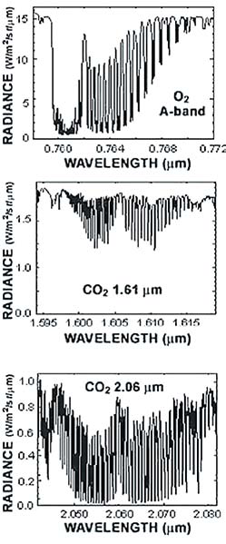
Last, but not least, the strong CO2 wavelength channel, in the vicinity of 2.06 µm, will provide a second and totally independent measure of the CO2 abundance. The 2.06 µm band spectra are very sensitive to the presence of aerosols. The ability to detect and mitigate aerosol presence enhances the accuracy of Xco2. The 2.06 µm band measurements are also sensitive to variations in atmospheric pressure and humidity along the optical path. These variations in pressure and humidity have a known impact on Xco2.
OCO-2 will fly in a polar, sun-synchronous orbit, providing global coverage with a 16-day repeat cycle. On each orbit, the Observatory path will cross the equator at approximately 1:35 p.m. local time. Acquisition at this time of day is ideal for spectroscopic observations of CO2 that use reflected sunlight as the high sun maximizes the measurement signal-to-noise ratio. Furthermore, since Xco2 measurements tend to be near their daily average value at this time of day, the Observatory data will be highly representative of the region where they were acquired.
Coordination of the orbit with the A-train facilitates carbon cycle science by integrating OCO-2 observations with those of other instruments that fly aboard the Aqua (http://aqua.nasa.gov/) and Aura (http://aura.gsfc.nasa.gov/index.html) spacecraft. Among these measurements are the temperature, humidity, and CO2
retrievals from Atmospheric Infrared Sounder (AIRS—http://www-airs.jpl.nasa.gov/), the cloud, aerosol and ocean color observations as well as carbon source and sink measurements from the Moderate Resolution Imaging Spectroradiometer (MODIS—http://modis.gsfc.nasa.gov/), and the CH4 and CO retrievals from Tropospheric Emission Spectrometer (TES—http://tes.jpl.nasa.gov/).
To enhance the quality and to verify the validity of mission data, OCO-2 will collect science observations in Nadir, Glint, and Target Modes.
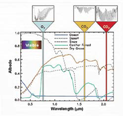
This diagram displays the spectral reflectance of common Earth surfaces at the wavelength of the three OCO-2 channels.
In Nadir Mode, the satellite points the instrument to the local nadir, so that data can be collected along the ground track just below the spacecraft. Science observations will be collected at all latitudes where the solar zenith angle is less than 85 degrees. Nadir Mode provides the highest spatial resolution on the surface and is expected to return more usable soundings in regions that are partially cloudy or have significant surface topography. Nadir observations may not provide adequate signal to noise over dark ocean surfaces.
In Glint Mode, the spacecraft points the instrument toward the bright “glint” spot, where solar radiation is specularly reflected from the surface. At high latitudes over the ocean, observations of the bright glint spot provide up to 100 times as much signal as measurements collected while looking straight downward at the ocean surface. Thus, the use of glint measurements significantly improves the signal to noise ratio over the dark ocean.
Glint soundings will be collected at all latitudes where the local solar zenith angle is less than 75 degrees. The OCO-2 mission plans to alternate between Nadir and Glint Modes over sequential 16-day global ground track repeat cycles so that the entire Earth is mapped in each mode on, roughly, monthly time scales.
In Target Mode, the Observatory will lock its view onto a specific surface location, and will retain that view while flying overhead. A target track pass can last for up to nine minutes. Over that time period, the Observatory can acquire as many as 12,960 samples at local zenith angles that vary between 0 degrees and 85 degrees.
The mission plans to conduct regular Target track passes over each of the OCO-2 calibration sites where the ground-based solar-looking Fourier Transform Spectrometers are located. Comparison of space-based and ground-based measures provides a means to identify and correct systematic and random errors in the OCO-2 Xco2 data products.
OCO-2 Specs
Orbit: 705 km/98.2 degrees Inclination
Power: 521 W orbit average
Launch Mass: 447 kg (985 lbs)
Solar Arrays: 813 W EOL, single axis articulated arrays
Stabilization: 3-axis, zero momentum, nadir and target pointing
Design life: 24 months
Editor’s note:
Our thanks to United Launch Alliance (www.ulalaunch.com), Orbital Sciences Corporation (http://www.orbital.com/) and NASA’s Jet Propulsion Laboratory (http://www.jpl.nasa.gov/) for their assistance, copy and the imagery used in this article.


